
Exhaust gas purification system

a technology of exhaust gas and purification system, which is applied in the direction of exhaust treatment electric control, electrical control, separation process, etc., can solve the problems of increasing the fuel consumption rate, enlarging the engine output, and affecting the operation of the operator, so as to save labor hours, facilitate the operation, and ensure the effect of operation

Active Publication Date: 2016-03-10
YANMAR POWER TECHNOLOGY CO LTD
View PDF10 Cites 1 Cited by
  • Summary
  • Abstract
  • Description
  • Claims
  • Application Information

AI Technical Summary

Benefits of technology

The present invention aims to solve the problem of discomfort experienced by operators due to sudden changes in engine torque. Additionally, the invention provides a solution to improve the engine exhaust gas purification device by eliminating the need for operators to manually change modes after emergency renewing modes. This saves time and reduces the workload for operators.

Problems solved by technology

However, since it is necessary to enhance an exhaust gas temperature (apply a thermal energy to the exhaust gas) in the case the DPF is renewed in the conventional structure, a fuel consumption rate is increase to exceed an operating amount of an accelerator operating device such as a throttle lever and an accelerator pedal, thereby enlarging an engine output.
Accordingly, since there are generated a shock and a change of an engine sound which are caused by a fluctuation of the engine torque, an uncomfortable feeling is applied to an operator.
It is impossible to deny a possibility that the operator misidentifies the sudden shock and the change of the engine sound as an abnormality.
Accordingly, in an engine with a DPF, even if a DPF renewing motion is executed by rising an exhaust gas temperature, there may be a case that a DPF purifying capacity is not sufficiently recovered (a case that the renewal is not sufficient).
However, in the case that a drive state in which a sufficient temperature rising action can not be obtained, for example, even by executing a post injection continues, the PM is excessively deposited within the DPF.
In the case that the DPF renewing motion is executed under the condition mentioned above, there is brought about an adverse effect that a crack is generated in the DPF or the DPF is melted away due to a rapid combustion of the PM which is excessively deposited.

Method used


Image

  • Exhaust gas purification system
  • Exhaust gas purification system
  • Exhaust gas purification system

Examples


Embodiment Construction

[0035]A description will be given below of an embodiment which embodies the present invention on the basis of the accompanying drawings.

(1) Engine and Peripheral Structure of the Same

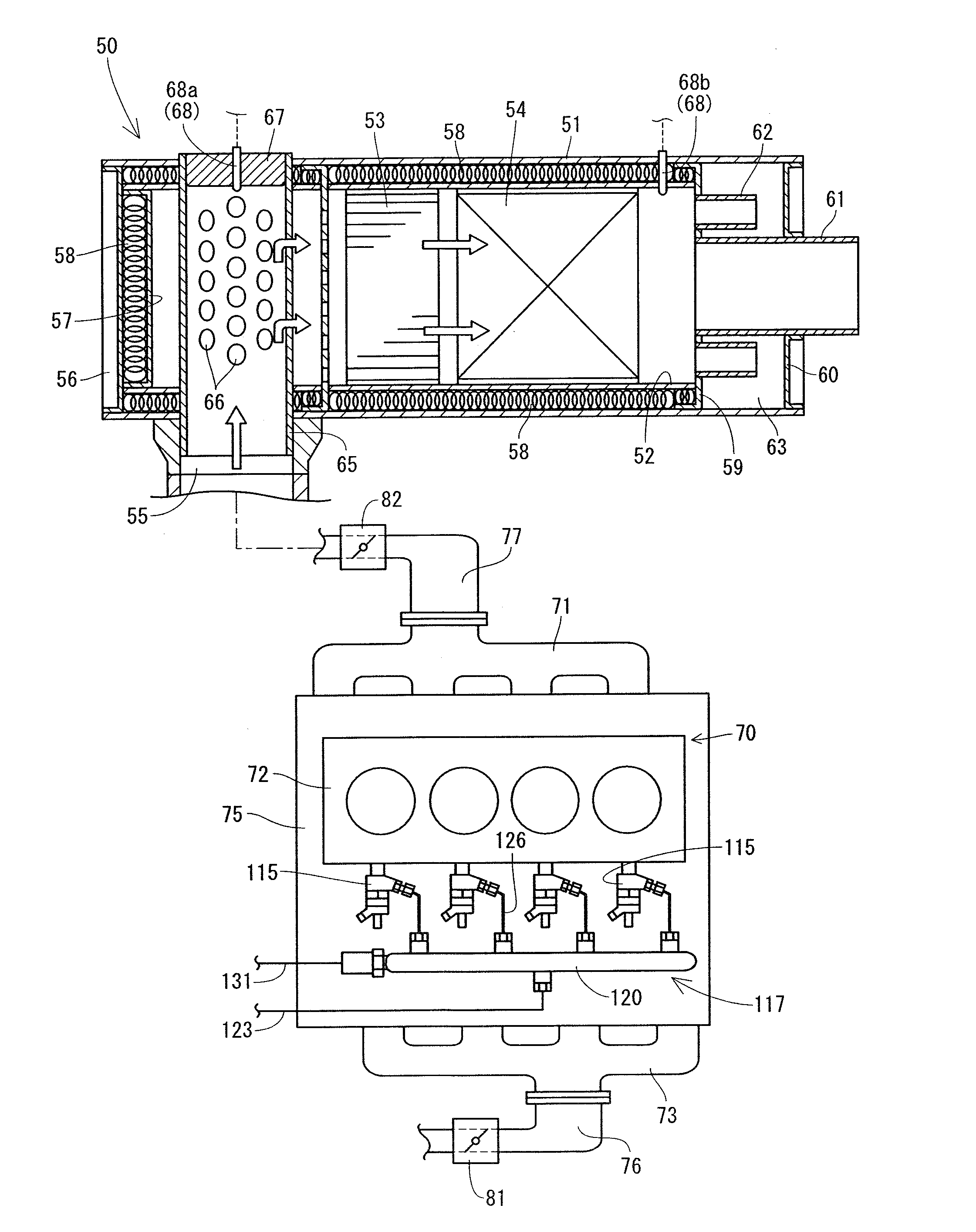
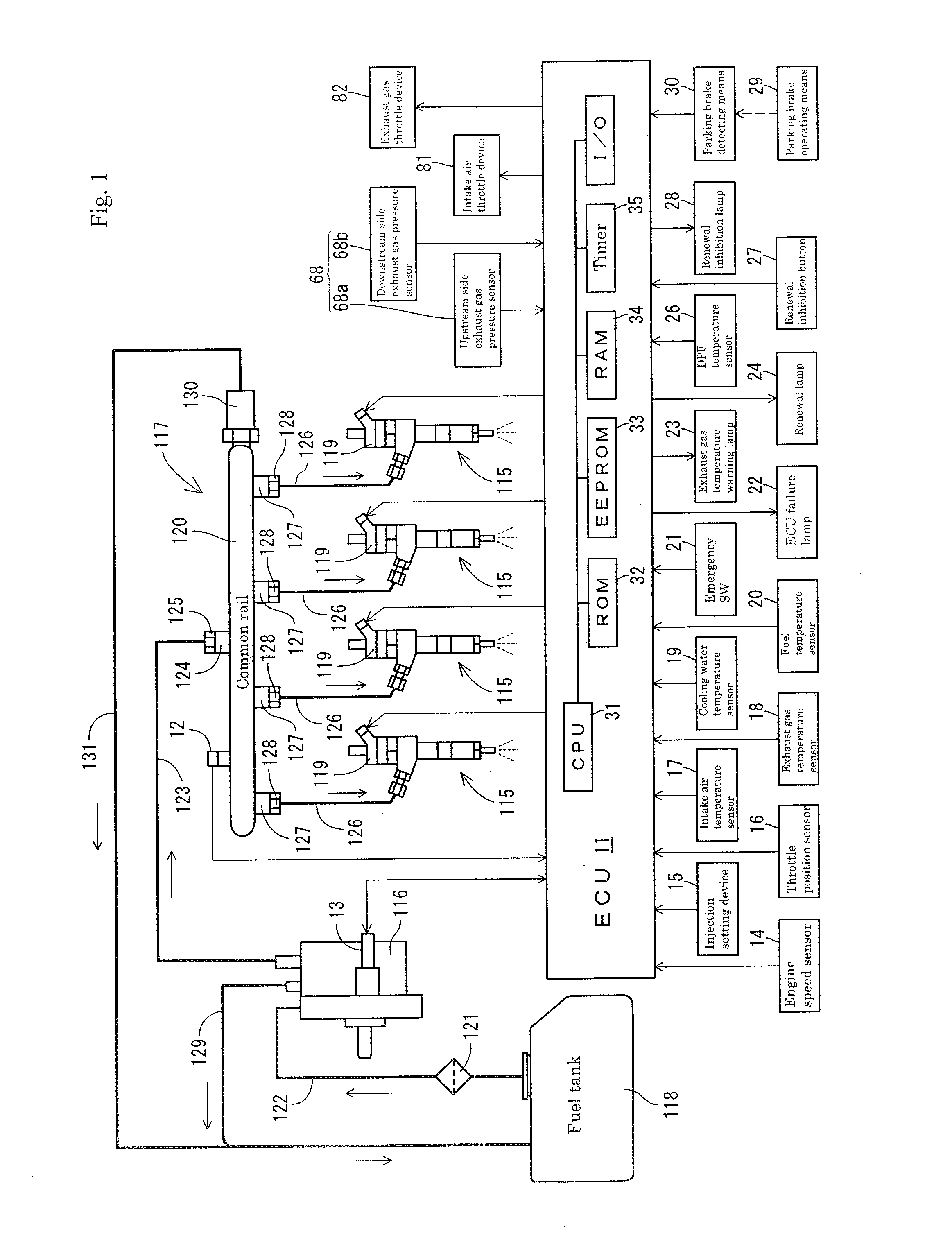
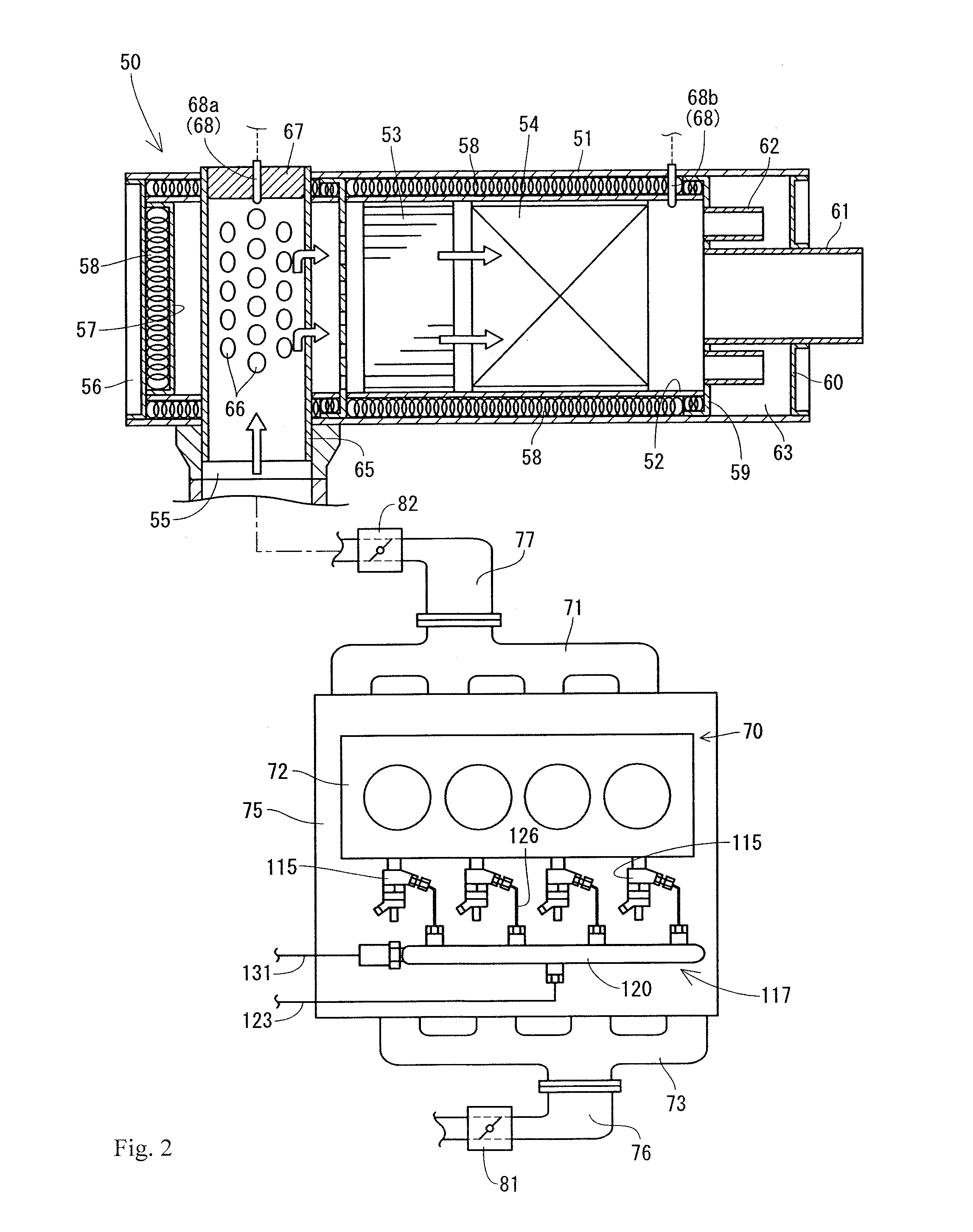
[0036]Next, a description will be given of the engine 70 and a peripheral structure of the same, with reference to FIG. 1 and FIG. 2. As shown in FIG. 2, the engine 70 is the four-cylinder type diesel engine, and is provided with a cylinder block 75 in which a cylinder head 72 is fastened to an upper face. An intake manifold 73 is connected to one side face of the cylinder head 72, and an exhaust manifold 71 is connected to the other side face. A common rail system 117 which supplies a fuel to each of cylinders of the engine 70 is provided below the intake manifold 73 in a side face of the cylinder block 75. An intake air throttle device 81 for regulating an intake air pressure (an amount of intake air) of the engine 70 and an air cleaner (not shown) are connected to an intake pipe 76 which is connected...


PUM


Abstract

An exhaust gas purification system comprises an exhaust gas purification device which is arranged in an exhaust gas route of an engine, renewing devices for burning and removing a particulate matter within the exhaust gas purification device, renewal advance notifying means which is actuated in the case that a clogged state of the exhaust gas purification device becomes equal to or more than a prescribed level, and renewal informing means which informs of a fact that the renewing devices are under operation. The renewal advance notifying means is actuated before actuating the renewing devices.

Description

[0001]This is a Divisional application of U.S. Ser. No. 13 / 965,942 filed Dec. 12, 2012.BACKGROUND OF THE INVENTION[0002]The present invention relates to an exhaust gas purification system with respect to an engine which is mounted to a working machine, for example, a construction machine, an agricultural machine and an engine generator.[0003]In recent years, as an application of an emission control of a high order with regard to a diesel engine (hereinafter, refer simply to as an engine), it is going to be desired to mount an exhaust gas purification device which purifies an air pollutant in an exhaust gas, to a construction machine, an agricultural machine and an engine generator to which the engine is mounted. As the exhaust gas purification device, a diesel particulate filter (hereinafter, refer to as DPF) has been known (refer to Patent Documents 1 and 2). The DPF is provided for collecting a particulate matter (hereinafter, refer to as PM) or the like. In this case, if the PM w...

Claims


Application Information

Patent Timeline
Patent Type & Authority Applications(United States)
IPC IPC(8): F01N9/00F01N3/025F01N3/035F01N13/00
CPCF01N9/002F01N13/009F01N3/0253F01N3/035F01N3/103F01N11/002F01N13/0097F01N2430/085F01N2470/02F01N2550/04F02D41/025F02D41/029F02D41/405F02D2041/228F02D2200/0812Y02T10/40B01D53/92F01N3/02F01N3/023F01N3/10F01N3/18F02D45/00
Inventor NOMA, YASUOOOHASHI, HIROSHIOHTA, ATSUSHIFUKUDA, TOMOHIROTOGASHI, TAICHI
Owner YANMAR POWER TECHNOLOGY CO LTD
Learn More