Advanced solar thermally driven power system and method

a solar thermal and power system technology, applied in the direction of machines/engines, mechanical equipment, light and heating equipment, etc., can solve the problems of high cost, inefficiency, and large number of relatively expensive solar photovoltaic panels to be utilized, and achieve high absolute humidity, reduce pollution, and high volumetric flow rate

Inactive Publication Date: 2016-03-10
PETERBROD
View PDF10 Cites 7 Cited by
  • Summary
  • Abstract
  • Description
  • Claims
  • Application Information

AI Technical Summary

Benefits of technology

[0041]Herewith finally, after passing through the humidifying air recuperator, it is possible to obtain a working airflow with a significantly high absolute humidity, and accordingly with a significantly high volumetric flow rate, before introducing thereof into the gas turbine. As a result, a thermal efficiency for this solar thermally driven power system is more than 70% (about 75%) in comparison with traditional solar thermally driven power systems that operate with an efficiency of only 20%-30%.
[0042]Also, when the proposed solar thermally driven power system is working in a thermal mode, using the solar air heater together with an auxiliary natural gas burner, its combustion process through va...

Problems solved by technology

First, the electrical energy output per area of a photovoltaic panel is very low so that a large number of relatively expensive solar photovoltaic panels must be utilized in order to generate an economically viable quantity of electricity.
Conventional solar photovoltaic systems for producing electricity traditionally have an efficiency rate of only 12%-15%, the most efficient ones of 25-35%, i.e. they are expensive and not efficient.
Also, the solar photovoltaic panels have a second disadvantage in that they do not provide power when there is little or no available solar energy, hence they may satisfactorily operate in cooperation with a utility grid to avoid power interruptions of energy consumers.
A disadvantage of solar-heated water turbine systems is that such systems are very expensive to produce.
However, this known solar system has a low the...

Method used


Image

  • Advanced solar thermally driven power system and method
  • Advanced solar thermally driven power system and method
  • Advanced solar thermally driven power system and method

Examples


Embodiment Construction

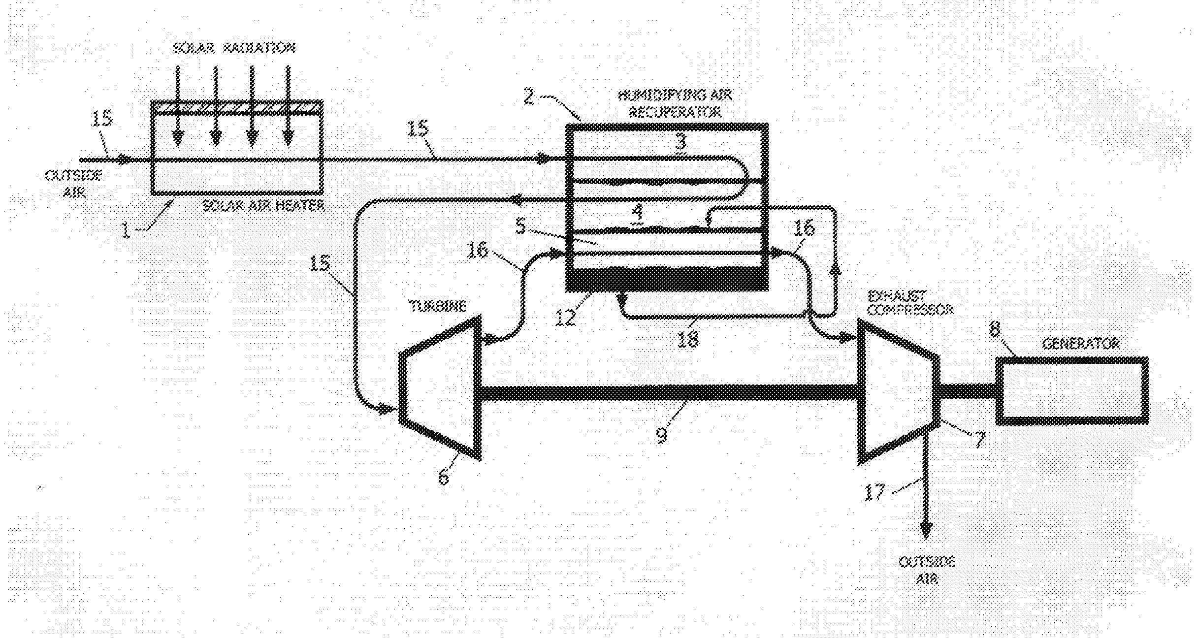
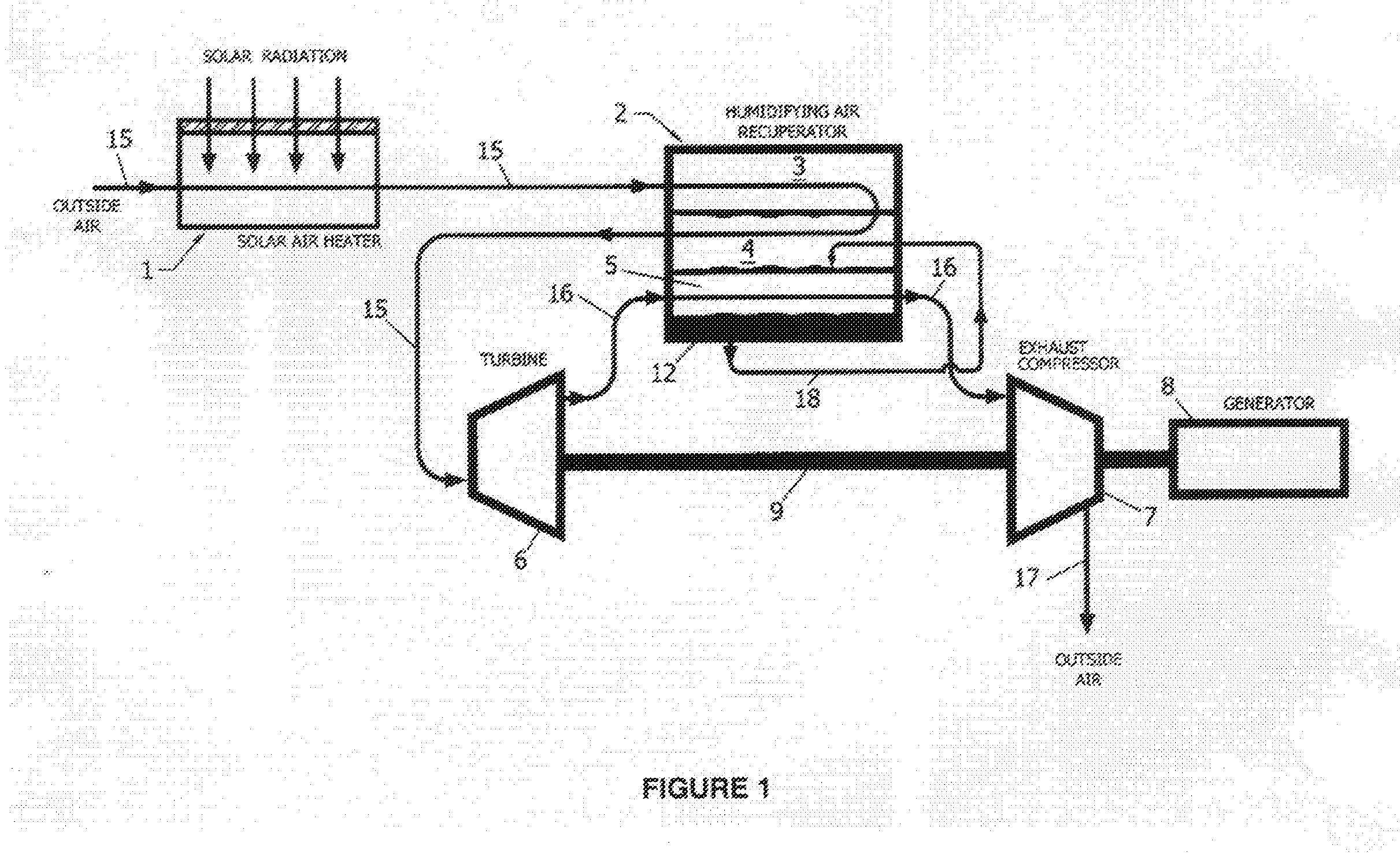
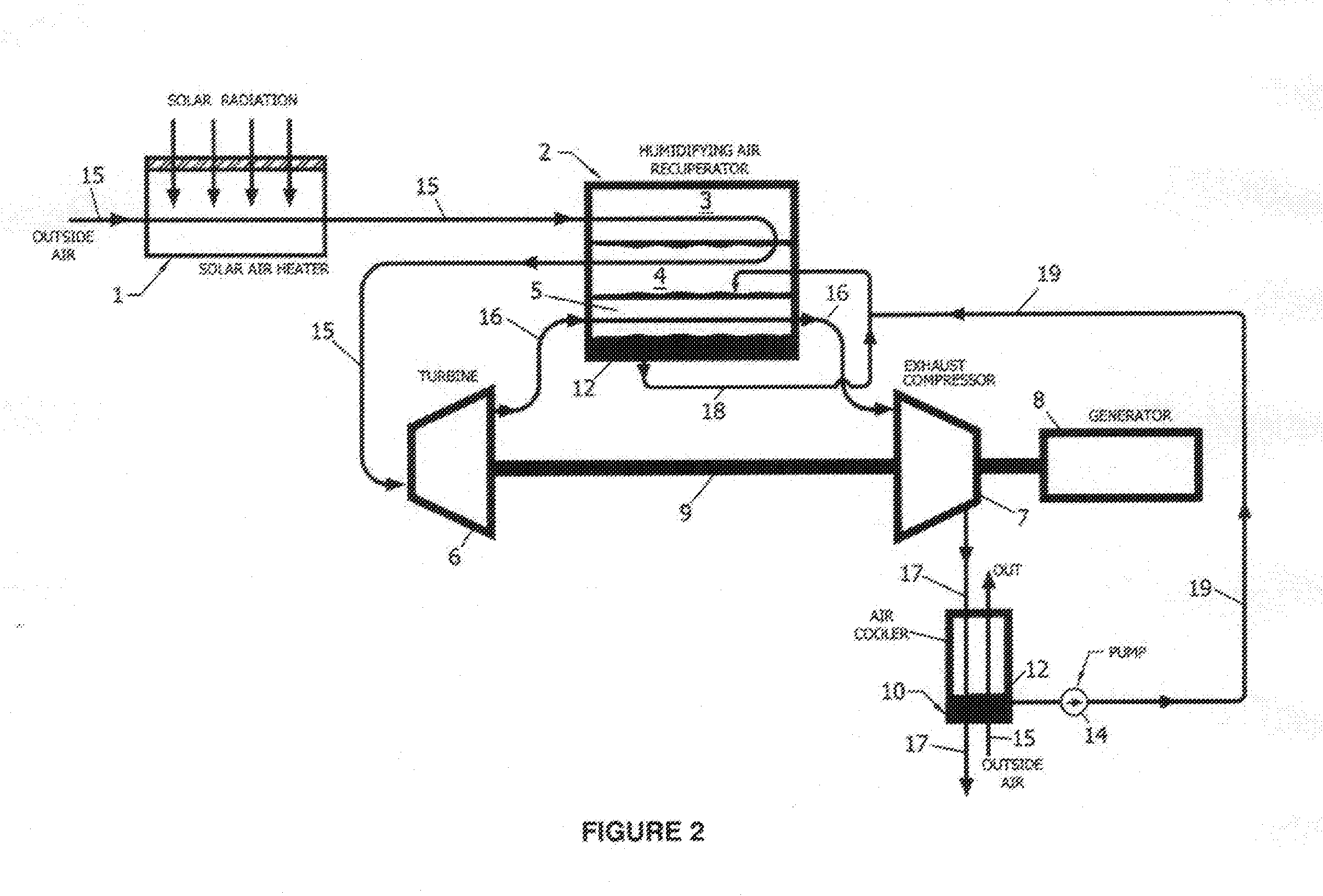
[0054]Below is a table of reference numbers and elements used in the description below.

ReferenceNumeralElement1Solar air heater2Humidifying air recuperator3Dry working channel4Wet working channel5Product channel6Gas turbine7Exhaust compressor8Electrical generator9Shaft10Air cooler12Condensate14Water pump15Airflow (outside or working air)16Product stream after the gas turbine17Product stream after the exhaust compressor18Water line for transport of the condensatefrom the product channel for wetting thewet working channels of the humidifyingair recuperator19Water line for transport condensate froman air cooler for wetting the wet workingchannels of the humidifying air recuperator20Auxiliary natural gas combustion chamber21Natural gas burner22Natural gas input23-27Valves28Heat accumulator30Solar desorber31Dry channel32Wet channel34Outside air for the solar desorber35Weak absorbent (desiccant)36Strong absorbent (desiccant)37Additional cooler38Condensing channel39Cooling channel40Outside...


PUM


Abstract

A proposed thermally driven solar power generating system includes a solar air heater receiving an airflow, a gas turbine driving a generator and at least one exhaust compressor, a humidifying air recuperator communicating with the heater. The recuperator includes a water pipeline, product channels, dry working channels, wet working channels connected with the dry channels, having pair-wise heat transfer relations. The airflow passes via the dry and wet channels, a portion thereof moves and expands through the turbine converting into a product stream, drawn into the product channels, cooled and condensed there. Condensate water moves from the product channels and pipeline into the wet channels. The product stream is sucked by the compressor and converted into a product air stream discharged therefrom. In embodiments, it incorporates an air cooler, auxiliary burner chamber, heat accumulator, solar desorber, additional cooler or M-Cooler, heat exchangers communicating with a number of the exhaust compressors.

Description

CROSS-REFERENCE TO RELATED APPLICATIONS[0001]This application is a U.S. national stage application of a PCT application PCT / US2013 / 077729 filed on 25 Dec. 2013, whose disclosure is incorporated herein in its entirety by reference, which PCT application claims priority of U.S. patent applications Nos. 61 / 827,835 filed on 28 May 2013 and 61 / 906,605 filed on 20 Nov. 2013.FIELD OF THE INVENTION[0002]The proposed invention relates to the field of solar thermally driven systems usable for generating power.BACKGROUND OF THE INVENTION[0003]Renewable resource as solar energy is critical to the future of our planet. Solar energy and the psychrometric energy (energy from air) obtained through an efficient heat recovery process known as Maisotsenko Cycle (herein further referred to as ‘M-Cycle’, e.g., see: Clean Air, Vol. 9, pp. 1-18, 2008 Copyright—2008 by Begell House, Inc.) can operate in synergy with each other and, together, they could provide an efficient solution for power generation, us...

Claims


Application Information

Patent Timeline
IPC IPC(8): F03G6/04F24S90/00F02C1/00F02C3/04
CPCF03G6/04F02C3/04F02C1/00F01K21/04F02C1/05F02C6/06F02C6/18F02C7/08Y02E10/46
Inventor BRODETSKY, PETER
Owner PETERBROD
Why Eureka
Try Eureka