Solid carbon dioxide absorbent composition and solid carbon dioxide absorbent containing the same

a technology of absorbent and carbon dioxide, which is applied in the direction of dispersed particle separation, other chemical processes, separation processes, etc., can solve the problems of high recovery cost, inability to prepare absorbent techniques, and inability to use large-scale industry methods, etc., to improve the carbon dioxide removal rate, improve the sorption capacity of carbon dioxide, and improve the regeneration capacity of absorben

Inactive Publication Date: 2016-03-24
KOREA ELECTRIC POWER CORP
View PDF4 Cites 8 Cited by
  • Summary
  • Abstract
  • Description
  • Claims
  • Application Information

AI Technical Summary

Benefits of technology

[0011]A solid carbon dioxide absorbent composition according to the present invention may significantly improve carbon dioxide sorption capacity as well as regeneration capacity of the absorbent in a high concentration carbon dioxide atmosphere. Accordingly, since the purity of carbon dioxide recovered from a regeneration reactor as well as carbon dioxide removal rate is improved, carbon dioxide is removed in high purity without the dilution of the removed carbon dioxide. Thus, storage and compaction of carbon dioxide may be simplified and economic efficiency may be improved.
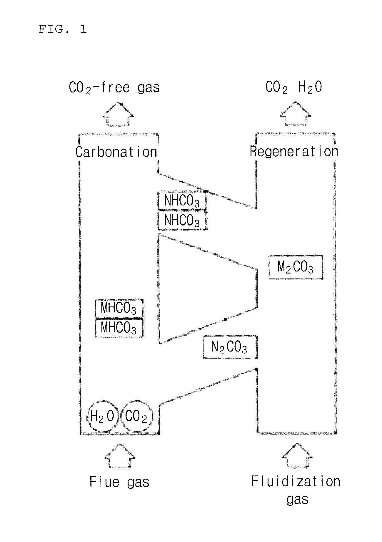
[0012]Also, a solid carbon dioxide absorbent of the present invention may reduce energy consumption required for the process by performing an absorption reaction in a flue gas temperature range (40° C. to 100° C.) and minimizing the supply of additional heat source required for regeneration (regeneration reaction temperature range: 100° C. to 200° C.), and thus, energy efficiency improvement and cost issues may be simultaneously addressed.

Problems solved by technology

However, these methods have limitations in that recovery costs may be high or these methods may be difficult to be used in large-scale industry.
Thus, these techniques are not suitable for preparing an absorbent in large quantities because preparation methods are different from each other, for example, preparation by physical mixing or preparation by an impregnation method, and, in particular, these techniques are not suitable for being used in a process in which solid absorbent particles capture and separate carbon dioxide while continuously circulating two reactors of absorption and regeneration of a fluidized bed process.
Therefore, it is inefficient to apply these techniques to an industrial process for discharging a large amount of carbon dioxide, for example, power plant, steel, refining, and cement industries.

Method used


Image

  • Solid carbon dioxide absorbent composition and solid carbon dioxide absorbent containing the same
  • Solid carbon dioxide absorbent composition and solid carbon dioxide absorbent containing the same
  • Solid carbon dioxide absorbent composition and solid carbon dioxide absorbent containing the same

Examples


example 1

[0080]In the present example, a solid absorbent was prepared by preparing a composition including 40 wt % of potassium carbonate (K2CO3) as an active component; 14 wt % of alpha alumina (α-Al2O3), an alumina compound, (purity of 99% or more, powder form, average particle diameter of 5 μpm or less), 5 wt % of titania (purity of 90% or more, average particle diameter of 1 pm or less), and 12 wt % of zirconia (ZrO2) as a support; 5 wt % of pseudo-boehmite (alumina content of 75% or more, powder form, average particle diameter of 50 μm or less) and 5 wt % of Na-type bentonite (powder form, average particle diameter of 50 μm or less) as an inorganic binder; a mixture (purity of 90% or more, powder form, average particle diameter of 45 μm or less) of 6 wt % of CaO and 9 wt % of SiO2 as a calcium silicate precursor; and 4 wt % of cerium oxide (Ce2O3), among lanthanide oxides, as an additive in total 8 kg of solid raw material.

[0081]Distilled water was weighed so that a total weight of the ...

example 2

[0086]In the present example, a solid absorbent was prepared in the same manner as in Example 1 by preparing a composition including 40 wt % of potassium carbonate (K2CO3) as an active component; 15 wt % of alpha alumina (purity of 99% or more, powder form, d50=1 μm or less), 5 wt % of titania (purity of 90% or more, average particle diameter of 1 μm or less), and 12 wt % of zirconia (ZrO2) as a support; 5 wt % of pseudo-boehmite (alumina content of 75% or more, powder form, average particle diameter of 50 μm or less) and 5 wt % of Na-type bentonite (powder form, average particle diameter of 50 μm or less) as an inorganic binder; a mixture of 5 wt % of CaO and 8 wt % of SiO2 as a calcium silicate precursor; and 2.5 wt % of lanthanum oxide (La2O3) and 2.5 wt % of cerium oxide (Ce2O3), among lanthanide oxides, as an additive in total 8 kg of solid raw material.

example 3

[0087]In the present example, a solid absorbent was prepared in the same manner as in Example 1 by preparing a composition including 40 wt % of potassium carbonate (K2CO3) as an active component; 14 wt % of alpha alumina (purity of 99% or more, powder form, d50=1 μm or less), 3 wt % of gamma alumina (purity of 95% or more, powder form, d50 =6 μm or less, specific surface area of 150 m2 / g), 5 wt % of titania (purity of 90% or more, average particle diameter of 1 μm or less) , and 13 wt % of zirconia (ZrO2) as a support; 5 wt % of pseudo-boehmite (alumina content of 75% or more, powder form, average particle diameter of 50 μm or less) and 5 wt % of Na-type bentonite (powder form, average particle diameter of 50 μm or less) as an inorganic binder; and a mixture (purity of 90% or more, powder form, average particle diameter of 45 μm or less) of 6 wt % of CaO and 9 wt % of SiO2 as a calcium silicate precursor in total 8 kg of solid raw material.


PUM

PropertyMeasurementUnit
temperatureaaaaaaaaaa

Abstract

The present invention relates to a solid carbon dioxide absorbent composition for removing carbon dioxide, and includes an active material, a support, and an inorganic binder, wherein the support relates to the solid carbon dioxide absorbent composition including an aluminum compound and two or more kinds of tetravalent metal oxides.

Description

TECHNICAL FIELD[0001]The present invention relates to a solid carbon dioxide absorbent composition capable of effectively removing carbon dioxide from gas containing carbon dioxide and a solid carbon dioxide absorbent containing the same. The solid absorbent of the present invention may be suitable for a dry regeneration CO2 capture process in which carbon dioxide formed by burning fossil fuels, such as coal and biomass, is removed by a method of contacting a solid with gas at a temperature of 250° C. or less.BACKGROUND ART[0002]As a method of removing carbon dioxide from a large-scale carbon dioxide generation facility, there are various methods such as wet chemical absorption, absorption, membrane separation, and cryogenic separation. However, these methods have limitations in that recovery costs may be high or these methods may be difficult to be used in large-scale industry.[0003]A carbon dioxide capture technique using a dry regenerated absorbent, which is recognized as an inno...

Claims


Application Information

Patent Timeline
Patent Type & Authority Applications(United States)
IPC IPC(8): B01J20/04B01D53/62B01D53/81
CPCB01J20/043B01D53/81B01D53/62B01D2257/504B01D2253/106B01D2253/1124B01D2258/0283B01D2253/104B01D53/96B01D53/82B01D53/83B01D2253/112B01D2253/25B01D2259/40088B01J20/041B01J20/06B01J20/08B01J20/2803B01J20/3204B01J20/3236Y02A50/20Y02C20/40B01D53/14
Inventor EOM, TAE, HYOUNGRYU, CHONG, KULLEE, JOONG, BEOMBAEK, JEOM, INKIM, KYEONG, SOOK
Owner KOREA ELECTRIC POWER CORP
Why Eureka
Try Eureka