Amorphous alloy transformer iron core of three-dimensional triangle structure

a technology of amorphous alloy and transformer, applied in the direction of transformer/inductances, transformer/inductances details, electrical equipment, etc., can solve the problems of large core size, longer processing time, and heavy overall weight, and achieve the effect of reducing the consumption of amorphous alloy, increasing labor efficiency, and shortening processing tim

Inactive Publication Date: 2016-03-24
HAIHONG ELECTRIC CO LTD
View PDF0 Cites 0 Cited by
  • Summary
  • Abstract
  • Description
  • Claims
  • Application Information

AI Technical Summary

Benefits of technology

[0018]This invention relates to a triangular amorphous alloy 3D core for transformer. In structure, triangular amorphous alloy 3D core for transformer is made of three identical single frames with approximate semicircular cross section through special technique after combination of them. The cross sections of the three core limbs are approximate circular. And every single frame is wound with several sizes of amorphous alloy trapezoid strips consecutively and tightly to form a semicircular cross section. Compared with the traditional amorphous alloy core, the yoke of triangular amorphous alloy 3D core is more than 20% lighter, and its angle parts are lighter. Consequently, the consumption of amorphous alloy is greatly diminished. Moreover, there is no seam in the yoke of triangular amorphous alloy 3D core. Therefore, there is no need to open the yoke and then close it, and the coil of transformer could be wound directly around the core limbs. Consequently, the processing time is shorter and efficiency of labor is raised.
[0019]In performance, magnetic conduction direction of the amorphous alloy strips is exactly the same with the magne

Problems solved by technology

It has disadvantages like huger size of core, heavier overall weight, and longer processing time.
Additionally, the size design of transformer is prone to be restricted by amorphous alloy sheet width.
The cost of the amorphous alloy core above is higher.
Consequently, three-phase electric power distribution may be not symmetrical.
Additionally, lots of se

Method used


Image

  • Amorphous alloy transformer iron core of three-dimensional triangle structure
  • Amorphous alloy transformer iron core of three-dimensional triangle structure
  • Amorphous alloy transformer iron core of three-dimensional triangle structure

Examples


Embodiment Construction

[0028]A full and enabling discourse of this invention, integrating the appended figures, is set forth in the specification, in which:

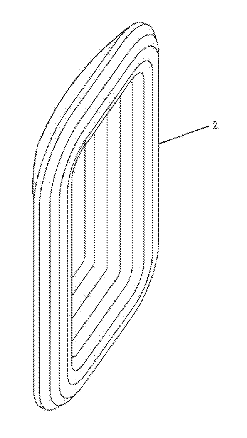
[0029]Showing in FIG. 1, a triangular amorphous alloy 3D core for transformer is made of three identical rectangle frames with approximate semicircular cross section,

[0030]Wherein its manufacturing method is comprised by following steps:
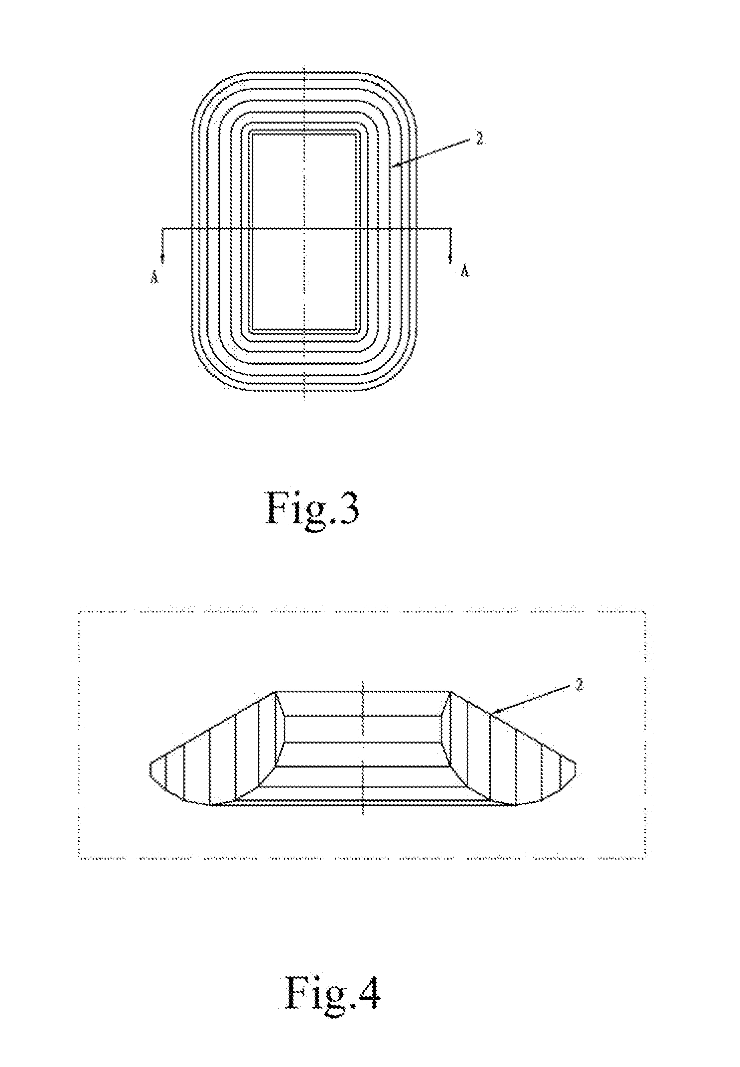
[0031](1) Slitting

[0032]The thickness of amorphous alloy material is usually 0.025 mm. Slit the rectangular amorphous alloy strips in fixed width into several sizes of trapezoid strips in the shape showing in FIG. 1.
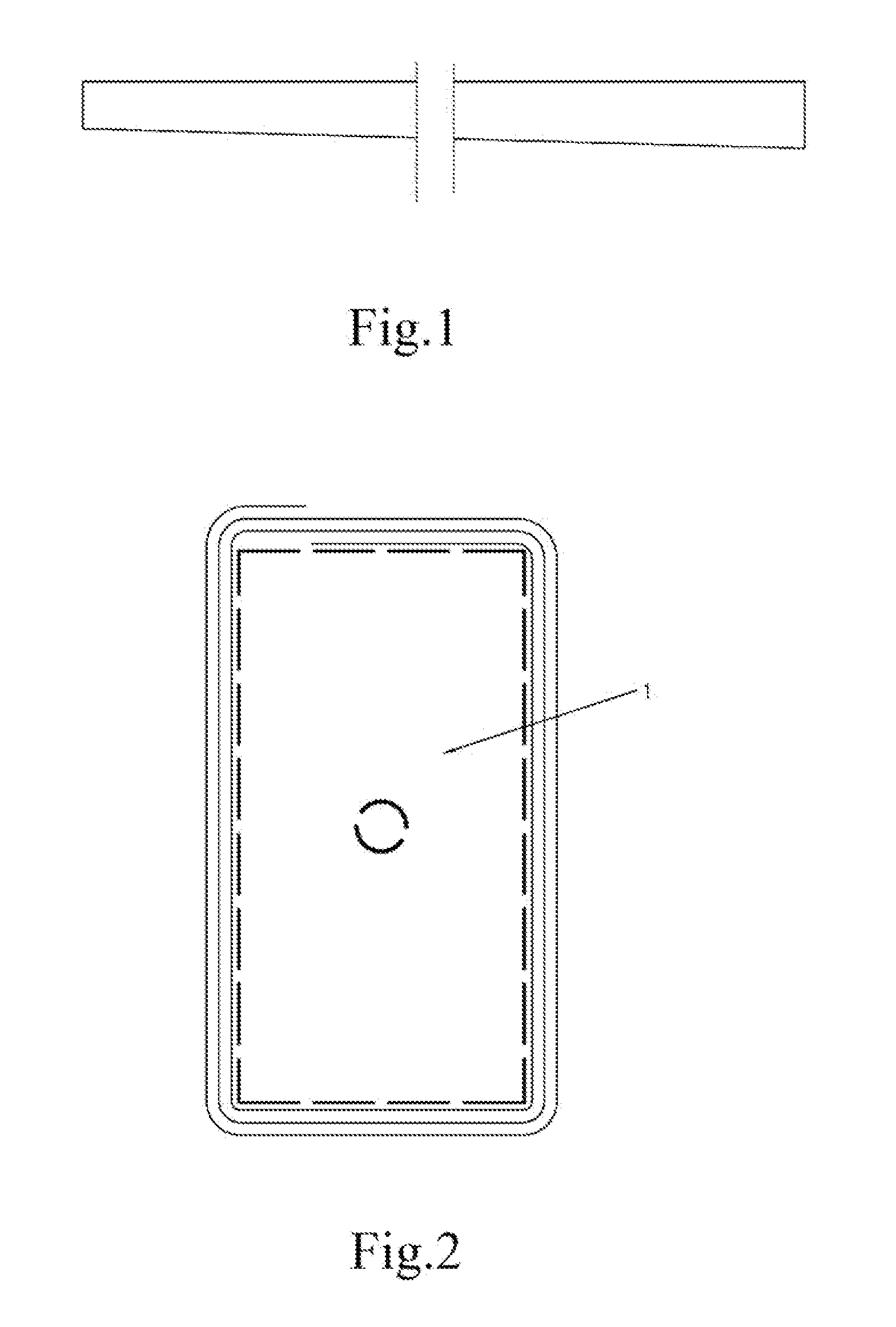
[0033](2) Winding

[0034]Rectangular mould 1, showing in FIG. 2, as inner support, starting from the first stage winding of the single frame, trapezoid strip is wound layer by layer from the inside out and make trapezoid strips in the winding machine follow the given direction, as a result, its upper and lower parts are outwardly inclined; after completion of the required thickness of the first stage winding, ...


PUM


Abstract

An amorphous alloy transformer iron core of a three-dimensional triangle structure belongs to the technical field of electrical devices. The amorphous alloy transformer iron core of the three-dimensional triangle structure is formed by piecing three identical rectangular single frames whose sections are approximately semicircular. A manufacturing method thereof comprises steps of cutting, winding, assembling, annealing and molding. The amorphous alloy transformer iron core of the three-dimensional triangle structure has the advantages of saving materials, reducing loss and noise, balancing three phases, enabling coils not to be sleeved, and being stable in performance and strong in anti-short circuit capacity.

Description

FIELD OF THE INVENTION[0001]This invention relates to a triangular amorphous alloy 3D core transformer, especially the manufacturing method of its core.BACKGROUND OF THE INVENTION[0002]Energy saving is an essential national policy of China to construct a conservation-oriented society. Due to the remarkable ability of amorphous alloy transformer to save energy and protect the environment, it has been gradually accepted by the majority of users and becomes an ideal new generation of distribution transformer. Currently, three-phase five-limb planar wound core and three-phase three-limb planar wound core are applied in amorphous alloy transformer on the market. The cross section of these two kinds of planar amorphous alloy cores for transformer is rectangle. It has disadvantages like huger size of core, heavier overall weight, and longer processing time. Additionally, the size design of transformer is prone to be restricted by amorphous alloy sheet width. The design and manufacture are ...

Claims


Application Information

Patent Timeline
IPC IPC(8): H01F27/26H01F3/04
CPCH01F27/263H01F3/04H01F41/0226
Inventor XU, KAIXUANGUO, XIANQING
Owner HAIHONG ELECTRIC CO LTD
Why Eureka
Try Eureka