Fossil-fuel power plant and fossil-fuel power plant operation method

a technology of fossil fuel power plants and power plants, applied in the direction of emission prevention, ignition automatic control, lighting and heating apparatus, etc., can solve the problems of reducing the performance of denitrification catalysts, affecting the efficiency of power generation, and increasing the cost of materials

Active Publication Date: 2016-03-31
ELECTRIC POWER DEVELOPMENT COMPANY
View PDF2 Cites 7 Cited by
  • Summary
  • Abstract
  • Description
  • Claims
  • Application Information

AI Technical Summary

Benefits of technology

[0034]The thermal power plant, which is an aspect of the present invention, includes the sub economizer between the high-pressure feed-water heater and the main economizer, in addition to the conventional economizer (main economizer). Thus, heat can be recovered from the exhaust gas after passage through the NOx removal equipment to the boiler feed-water. Therefore, power generation efficiency can be improved.

Problems solved by technology

However, the usage of these materials is still in a developing stage as the next generation of high temperature materials at this time, since there are plenty of problems to be solved, such as their manufacturability and material properties, in the usage of these materials.
In addition, these materials are more expensive than the currently standardized materials.
Thus, usage of these materials becomes an economical problem during actual plant construction.
Furthermore, in the case where the selective catalytic reduction NOx removal equipment is used as shown in FIG. 4, there is a problem in which the acidic ammonium sulfate is precipitated and the performance of the denitrification catalyst is reduced when the exhaust gas temperature at the inlet 114a of the NOx removal equipment 114 is low.
Because of this, there is a problem that recovery of the exhaust gas temperature by the economizer 136 cannot be done sufficiently.
Furthermore, while the exhaust gas after passage through the NOx removal equipment 114 is subjected to heat exchanging with the primary air and the secondary air in the regenerative air preheater 115, there is a limitation for the temperature effectiveness of the air preheater 115.
Therefore, the exhaust gas is released into the atmosphere from the chimney in the state where the potential heat of the exhaust gas from the boiler is not sufficiently recovered in the actual situation.
Thus, there is a problem that heat exchanging between the combustion air (the primary air and the secondary air) and the exhaust gas from the boiler is not performed in the maximum efficient.

Method used


Image

  • Fossil-fuel power plant and fossil-fuel power plant operation method
  • Fossil-fuel power plant and fossil-fuel power plant operation method
  • Fossil-fuel power plant and fossil-fuel power plant operation method

Examples


first embodiment

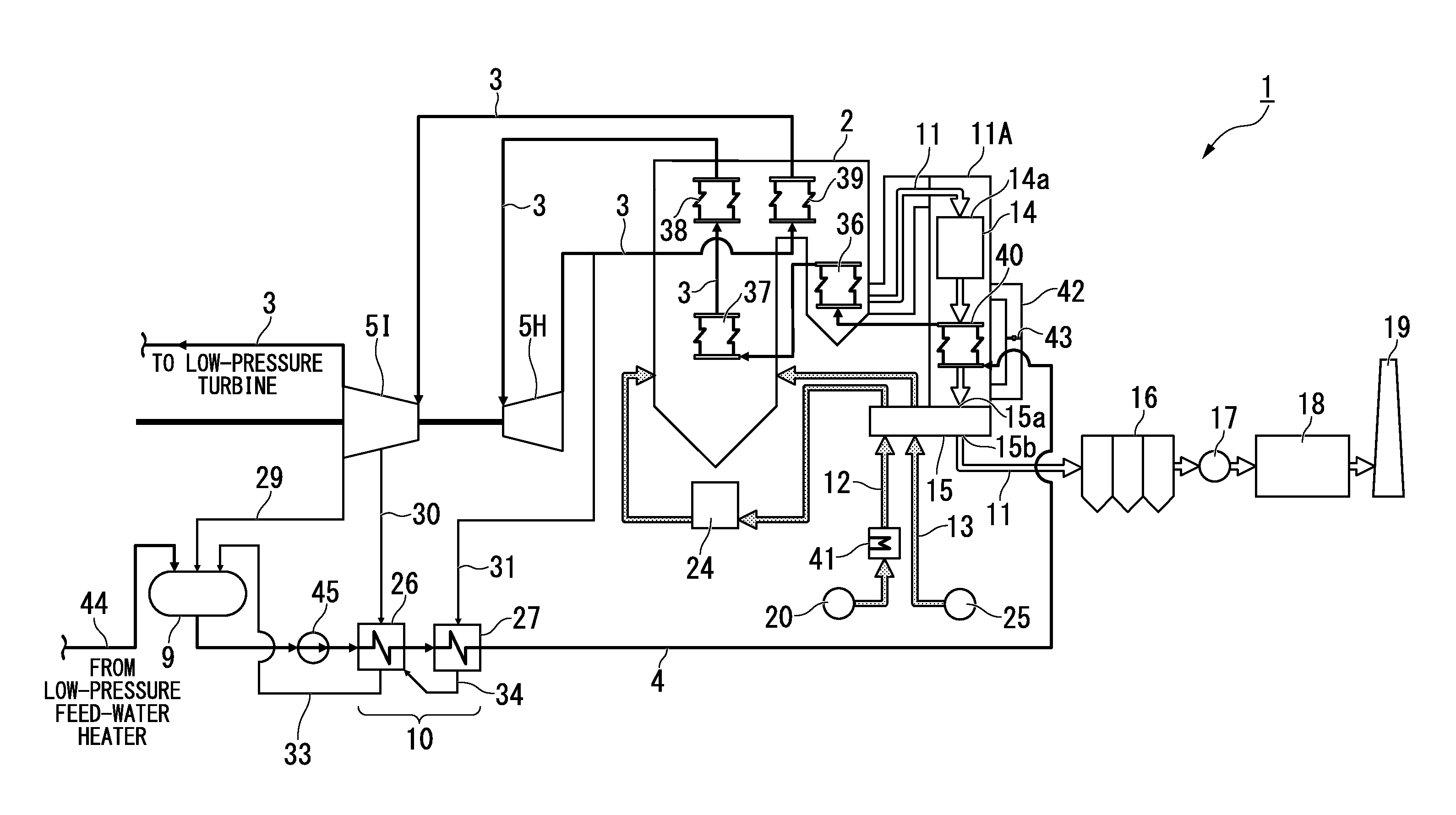
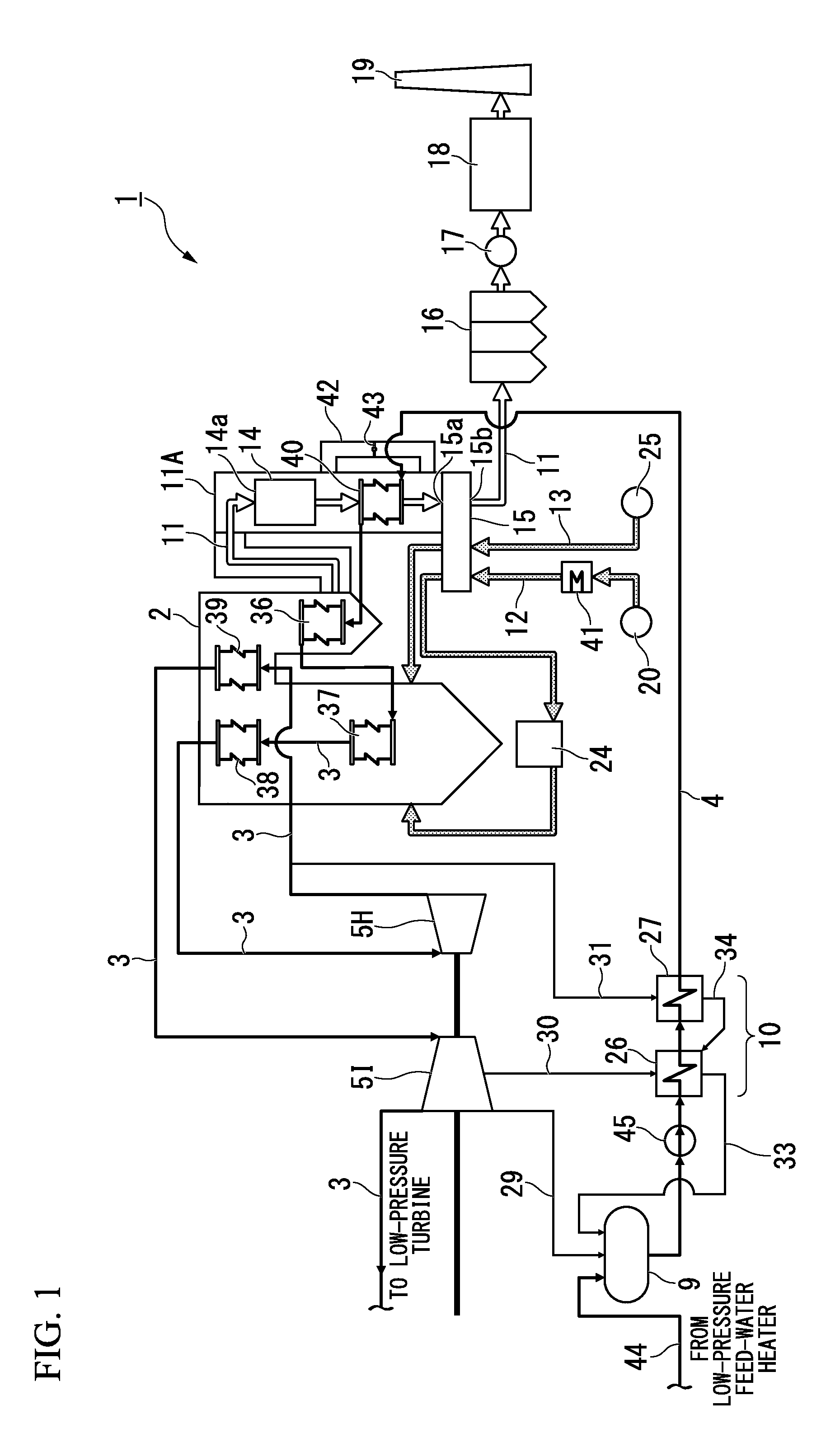
[0040]FIG. 1 is the system diagram showing an enlarged view around the boiler of the coal-fired power plant 1 (hereinafter referred as “plant”), which is the first embodiment of a thermal power plant that is an aspect of the present invention. In FIG. 1, descriptions of the electrical system, various wires, or the like are omitted for clarity of the arrangement of constituents contributing the regenerative reheating cycle.

[0041]First, the configuration of the plant 1 of the present embodiment is explained. As shown in FIG. 1, the plant 1 is generally constructed from the boiler 2; the exhaust gas system 11; the steam system 3; the feed-water system 4; the high-pressure feed-water heater 10; the main economizer 36; the NOx removal equipment 14; and the sub economizer 40. The boiler 2 increases the temperature of feed-water by using heat obtained by combusting the fuel to generate steam. The exhaust gas system 11 circulates the combustion gas exhausted from the boiler 2 as the exhaust...

second embodiment

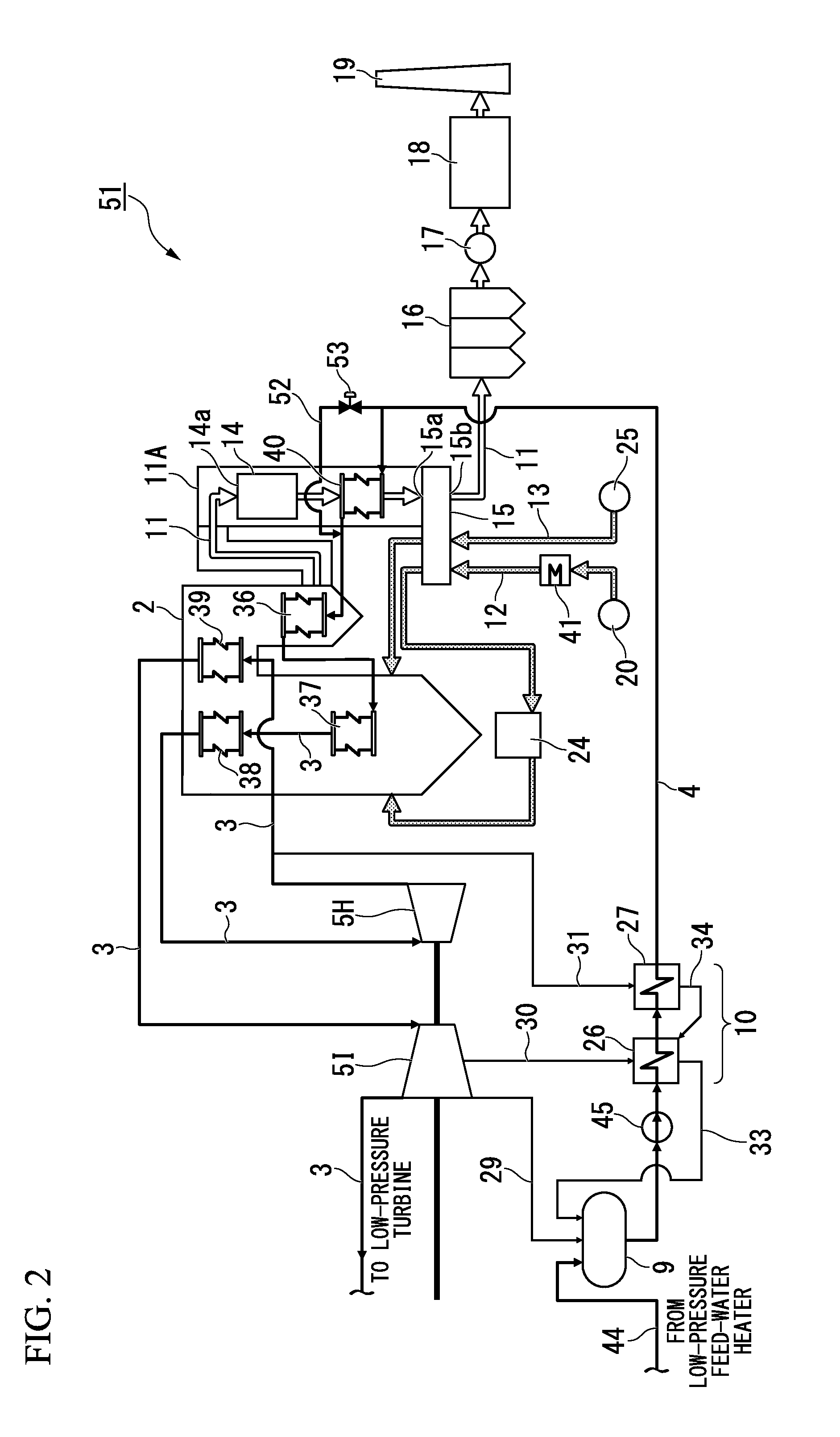
[0073]Next, the second embodiment, which is an aspect of the present invention, is explained. The present embodiment has different configurations to the plant 1 and the method of operating the plant 1 of the first embodiment. Therefore, the thermal power plant and the method of operating the thermal power plant of the present embodiment are explained by using FIG. 2. In the explanation, the same reference symbols as the first embodiment are used for the identical constituents to the first embodiment, and detail explanations for them are omitted.

[0074]The coal-fired power plant 51 of the present embodiment has the configuration in which the feed-water pipe 52; and the feed-water amount control valve 53, both of which corresponds to the exhaust gas temperature control device, replace the gas duct 42; and the gas amount control damper 43 (refer FIG. 1), both of which constitute the exhaust gas temperature control device in the plant 1 of the first embodiment as shown in FIG. 2.

[0075]Sp...

examples

[0084]Specific Examples are shown below.

[0085]Simulation of a coal-fired plant of 600,000 kW was performed and improving effect on the net thermal efficiency was confirmed.


PUM


Abstract

A thermal power plant has an exhaust gas system, a feed-water system, a high-pressure feed-water heater provided to the feed-water system, a main economizer, a catalytic NOx removal equipment, and a sub economizer. The main economizer is provided to the secondary side of the high-pressure feed-water heater of the feed-water system and increases the temperature of the feed-water by using the residual heat of the combustion gas from the boiler. The catalytic NOx removal equipment is provided to the secondary side of the main economizer of the exhaust gas system. The exhaust gas is supplied to the catalytic NOx removal equipment at a required temperature or higher. The sub economizer is provided between the high-pressure feed-water heater and the main economizer and increases the temperature of water by using the exhaust gas on the secondary side of the NOx removal equipment.

Description

TECHNICAL FIELD[0001]The present invention relates to a thermal power plant and a method of operating the thermal power plant.[0002]Priority is claimed on Japanese Patent Application No. 2013-109118, filed May 23, 2013, the content of which is incorporated herein by reference.BACKGROUND ART[0003]FIG. 3 is the system diagram showing an example of a configuration of a general thermal power plant described in Non Patent Literature 1 detailed below.[0004]As shown in FIG. 3, a general thermal power plant is generally constructed from the boiler 2; the steam system 3; the condensate system 44; and the feed-water system 4. The boiler 2 generates the combustion gas and combustion heat by combusting fuel such as coal, oil, or the like; and generates steam by increasing a temperature of feed-water by using the combustion heat. The steam system 3 has multiple steam turbines 5 and the condenser 6. Each of the steam turbines 5 is driven by the steam generated by the boiler 2. The steam exhausted...

Claims


Application Information

Patent Timeline
Patent Type & Authority Applications(United States)
IPC IPC(8): F22D1/38F22D1/02F22D1/32F23J15/00F23L15/02
CPCF22D1/38F23J15/00F22D1/32F22D1/02F23L15/02F23J15/02F23J15/06F23L11/00F23J2215/10F23J2219/10F01K7/22F01K7/40F22D1/34Y02E20/34
Inventor NAGANO, SHIROSUZUKI, SHINSUKE
Owner ELECTRIC POWER DEVELOPMENT COMPANY
Why Eureka
Try Eureka