
Flash evaporation of solid state battery component

a solid-state battery and flash evaporation technology, applied in the field of flash evaporation of solid-state battery components, can solve the problems of high surface area/mass ratio of very small particles, relatively short cycle life, and inability to use, and achieve the effect of improving rate performan

Active Publication Date: 2016-03-31
QUANTUMSCAPE BATTERY INC
View PDF6 Cites 4 Cited by
  • Summary
  • Abstract
  • Description
  • Claims
  • Application Information

AI Technical Summary

Benefits of technology

The patent text describes methods and systems for making materials for lithium batteries with small constituent separation distances. This allows the battery to operate with improved rate performance. The small distances also reduce the distance metal atoms must diffuse, which can improve the efficiency of the battery. However, small particles can face challenges with a high surface area / mass ratio, which can lead to the formation of a solid electrolyte interface (SEI) layer that can extract lithium from the battery and reduce its performance. The patent aims to address this challenge and provide better performance and cycle life for lithium batteries.

Problems solved by technology

An additional challenge to realizing the potential benefits of conversion materials arises from the high surface area / mass ratio of very small particles.
In some examples, the large surface area (as a function of the mass of reactive material) results in a relatively large fraction of the active material converting to a solid electrolyte interface (SEI) layer, which extracts much of the available lithium and presents it in an unusable form.
This also can result in a relatively short cycle life as the SEI layer may continue to grow in subsequent cycles.
The growing SEI contains mass that does not contribute to the energy stored in the battery, and may present a barrier to lithium transport, reducing the rate performance of the battery.

Method used


Image

  • Flash evaporation of solid state battery component
  • Flash evaporation of solid state battery component
  • Flash evaporation of solid state battery component

Examples


Embodiment Construction

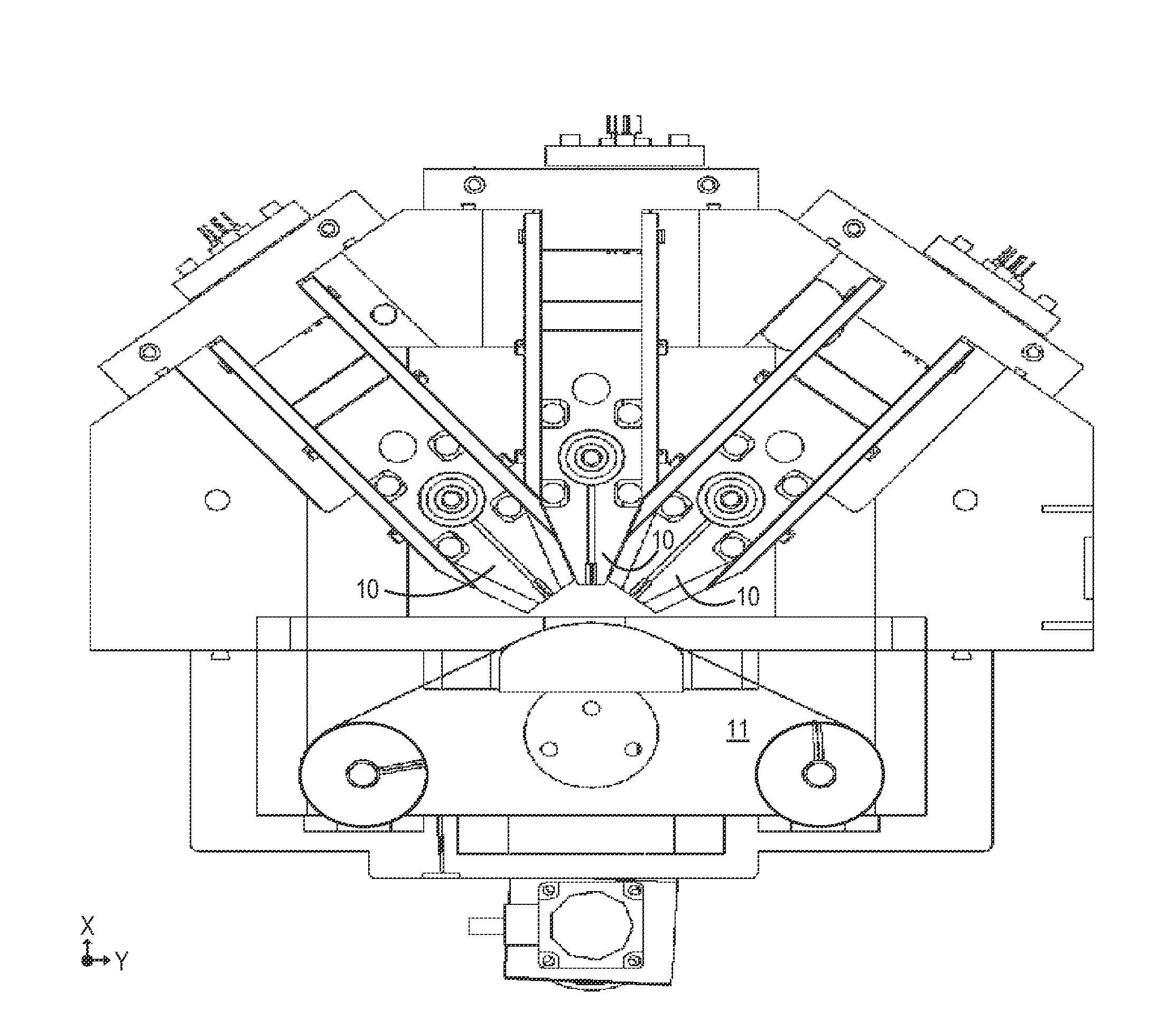
[0042]According to an example of the present invention, techniques related a manufacture of solid-state battery components having desired energy density are provided. In particular, the present invention provides techniques for manufacturing a cathode active material having a desired reactivity. More particularly, the present invention provides an apparatus and method for the formation of a plurality of particles with a selected composition that is useful for making a cathode material to improve the intermixing of elements to a desired level. Merely by way of example, the invention has been applied to solid state battery cells, although there can be other applications.

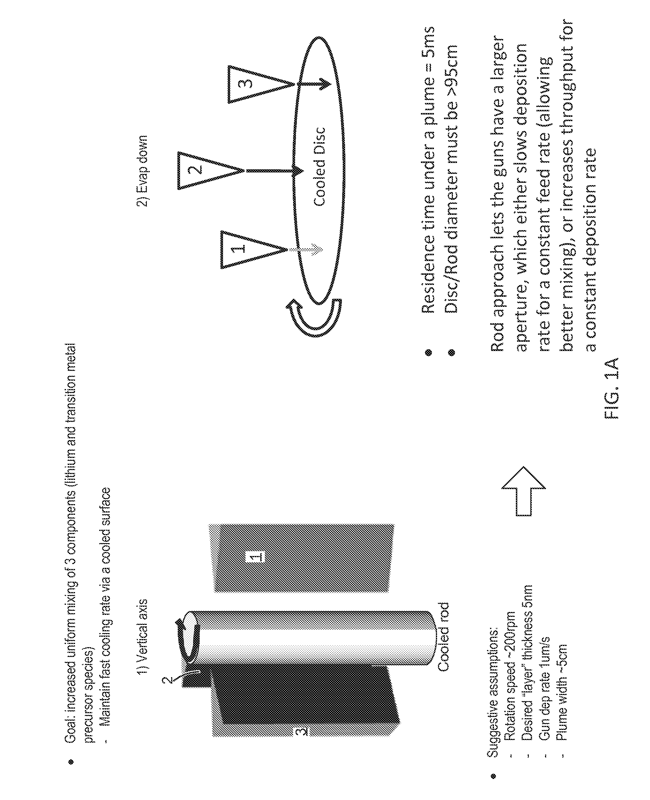
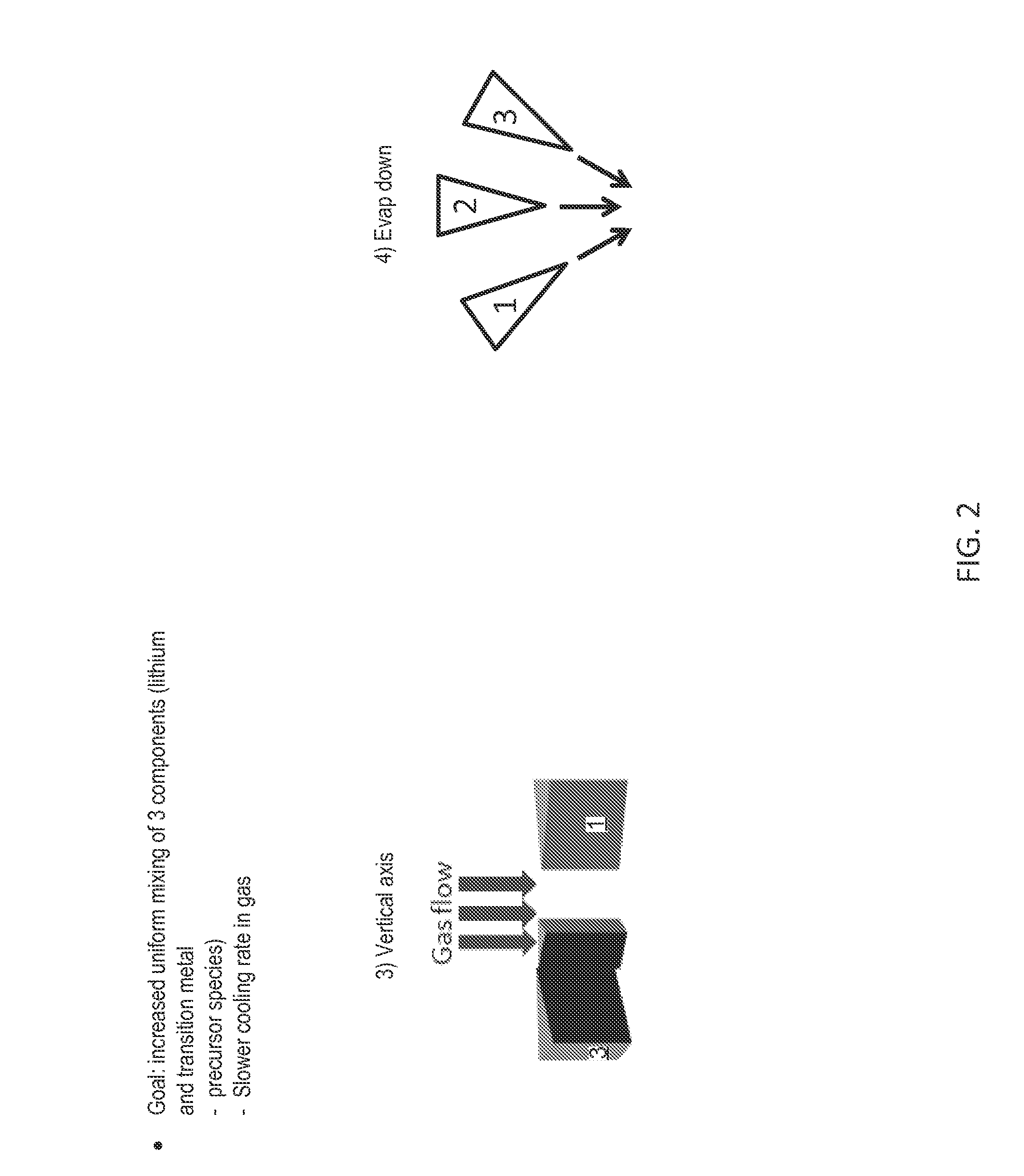
[0043]In one example, the present invention provides for the manufacture particles that are a mixture of LiF and a transition metal such as Cu, Ni, Co, Mn, and / or Fe. In certain examples, the manufactured particles include LiF and transition metal which are mixed at the nanoscale or even at the molecular / atomic level. ...


PUM

PropertyMeasurementUnit
Temperatureaaaaaaaaaa

Abstract

In an example, the present invention provides a method for forming a film of material for a solid state battery or other energy storage device. The method includes providing a first precursor species, and providing a second precursor species. The method also includes transferring the first precursor species through a first nozzle and outputting the first precursor species in a first molecular form and transferring the second precursor species through a second nozzle and outputting the second precursor species in a second molecular form. The method includes causing formation of first plurality of particles, ranging from about first diameter to about a second diameter, by intermixing the first precursor species with the second precursor species. The method also includes cooling the first plurality of particles at a rate of greater than 100° C. / s to a specified temperature.

Description

CROSS-REFERENCE TO RELATED APPLICATIONS[0001]This application claims priority to U.S. Provisional Patent Application No. 61 / 832,127, filed Jun. 6, 2013, the entire contents of which are herein incorporated by reference in its entirety for all purposes.BACKGROUND[0002]The present invention relates generally to solid-state battery techniques. In particular, the present invention provides techniques for manufacturing a cathode, a catholyte, an electrolyte, or combination thereof, material having a desired ion conductivity. More particularly, the present invention provides an apparatus and method for the formation of a plurality of nanodimensioned particles with a selected composition that is useful for making cathode, catholyte, electrolyte, or combination thereof, materials to improve the ionic conductivity, for example, in a solid state battery. Merely by way of example, the invention has been applied to solid-state battery cells, although there can be other applications.[0003]A high...

Claims


Application Information

Patent Timeline
IPC IPC(8): H01M4/04B22F1/054B22F1/08C23C14/24
CPCC23C14/24H01M4/0428C23C14/14C23C14/26C23C14/562B22F9/28B22F2999/00H01M4/139H01M4/582Y02E60/10B22F1/054B22F1/08B22F3/003C22C2200/02
Inventor STIMSON, BRADLEY, O.HERMANN, WESTON, A.BERKSTRESSER, DAVID, E.HOLME, TIMALLENIC, ARNOLD
Owner QUANTUMSCAPE BATTERY INC
Learn More