Polycarbonate resin composition for thin optical component, and thin optical component

Active Publication Date: 2016-05-05
MITSUBISHI ENG PLASTICS CORP
View PDF6 Cites 19 Cited by
  • Summary
  • Abstract
  • Description
  • Claims
  • Application Information

AI Technical Summary

Benefits of technology

[0043]The present invention can provide a polycarbonate resin composition for thin optical components, that presents no loss whatsoever of the properties of the polycarbonate resin itself and that exhibits a good transmittance and hue and a good resistance to thermal discoloration. The present invention can also provide thin optical components that exhibit a good transmittance and hue, and in particular the present invention can be favorably used for thin optical components as typified by light guide plates.
[0044]The polycarbonate resin pellet of the present invention, notwithstan

Problems solved by technology

Polycarbonate resins exhibit excellent mechanical properties, thermal properties, and electrical properties and an excellent weatherability; however, they have a lower light transmittance than PMMA and the problem thus arises of a lower brightness when a planar light source assembly is constructed of a light source and a polycarbonate resin light guide plate.
In addition, there has lately been demand for a small chromaticity difference between the incident light area of the light guide plate and locations distant from the incident light area, but a problem here is that polycarbonate resin more readily undergoes yellowing than does PMMA resin.
However, in the case of the method in Patent Document 1, while the addition of the acrylic resin does bring about a good hue, the light transmittance and brightness cannot be raised due to the appearance of cloudiness.
In the case of the methods in Patent Document 2 and Patent Document 3, an improvement in the flowability and transferability can be expected, but the problem occurs of a reduction in the heat resistance.
In such high-end light guide plates, the transmittance and YI level achieved by the ab

Method used


Image

  • Polycarbonate resin composition for thin optical component, and thin optical component
  • Polycarbonate resin composition for thin optical component, and thin optical component
  • Polycarbonate resin composition for thin optical component, and thin optical component

Examples


examples

[0184]The present invention is described more specifically by the following examples. However, this should not be construed as limiting the present invention to the following examples.

examples 8 to 14

, Comparative Examples 6 and 7, and Reference Examples 1 to 3

[0196]The starting materials used are as shown in Table 4 below.

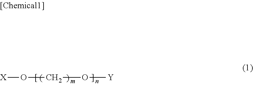
TABLE 4componentcodepolycarbonateA1aromatic polycarbonate resin for which bisphenolresin (A)A is a starting material, viscosity-averagemolecular weight = 14,000A2aromatic polycarbonate resin for which bisphenolA is a starting material, viscosity-averagemolecular weight = 12,500polyalkyleneB1polytetramethylene ether glycol given byether glycolHO(CH2CH2CH2CH2O)nH, n = 14,compound (B)product name: “PTMG1000”, from Mitsubishiwith formulaChemical Corporation(1)number-average molecular weight = 1,000B2polytetramethylene ether glycol given byHO(CH2CH2CH2CH2O)nH, n = 28,product name: “PTMG2000”, from MitsubishiChemical Corporationnumber-average molecular weight = 2,000phosphorusC1bis(2,6-di-tert-butyl-4-methylphenyl)stabilizerpentaerythritol diphosphite(C)product name: “Adeka Stab PEP-36”, fromADEKA CorporationC3bis(2,4-dicumylphenyl) pentaerythritoldiphosphite,produc...

example 15

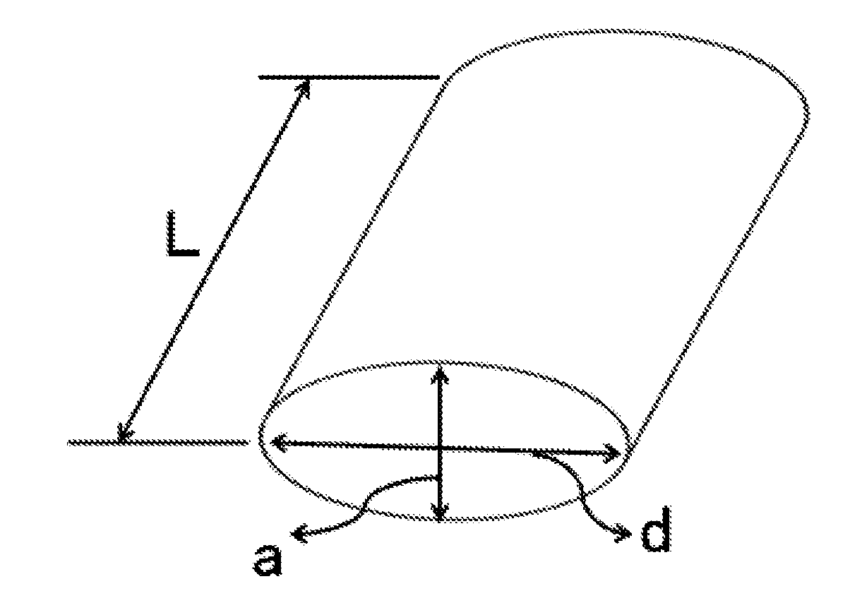
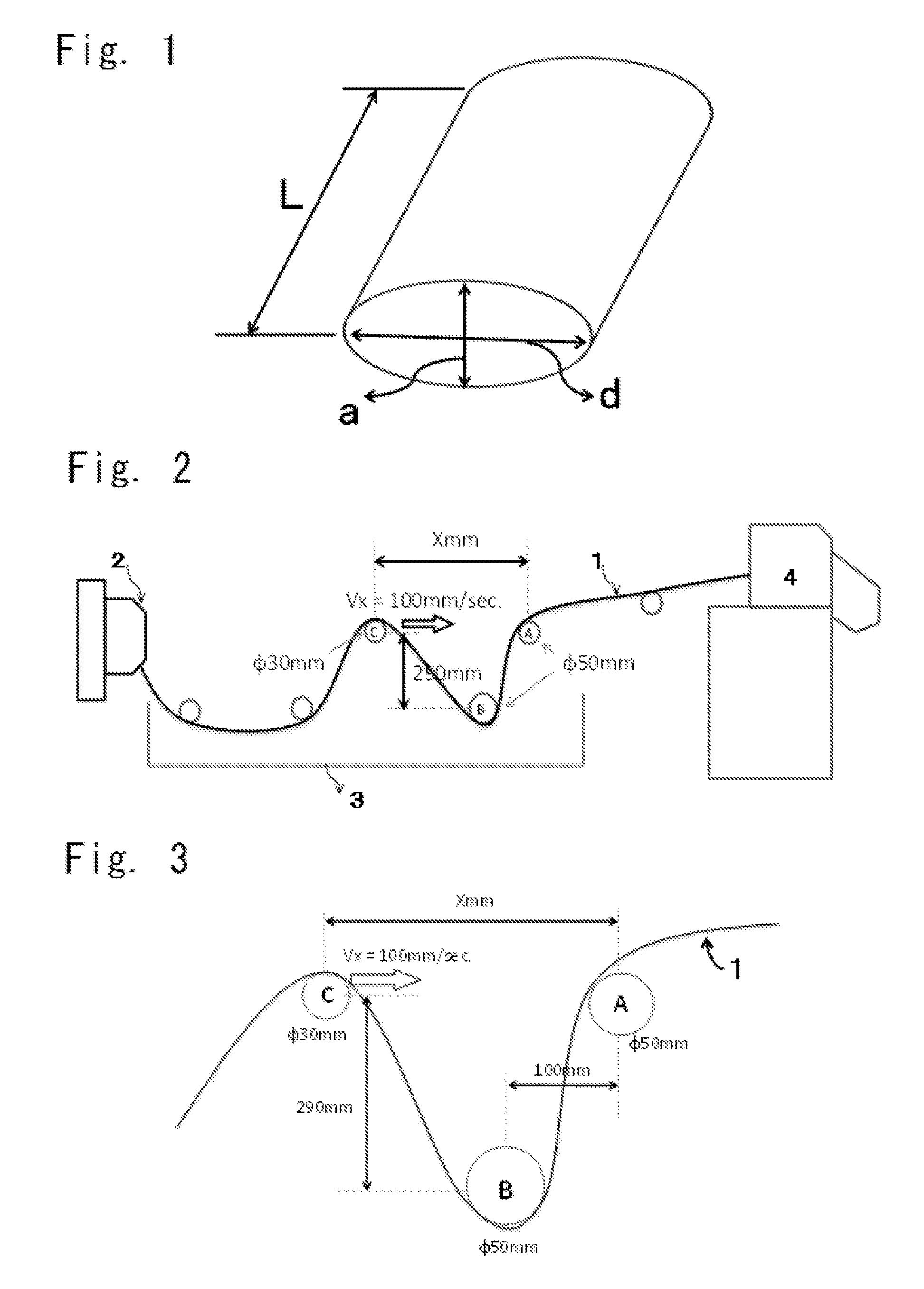
[0205]The components indicated in Table 1 were blended in the proportions (mass parts) given for Example 5 in Table 2 and were mixed for 20 minutes in a tumbler followed by continuous feed to a vented twin-screw extruder (“TEX44αII” from Japan Steel Works, Ltd.) from the hopper of the extruder and melt-mixing in the extruder and extrusion under the following extrusion conditions: cylinder temperature=240° C., extruding rate=150 kg / h, and screw rotation rate=250 rpm. The extrusion was carried out from an extrusion nozzle provided with a die having an elliptical die orifice with a major diameter of 6.5 mm and a minor diameter of 3.5 mm with its major diameter made horizontal, and was carried out into a strand shape with the major diameter of the elliptical cross-section thereof made approximately horizontal. Polycarbonate resin pellets were obtained by introduction into a cooling water bath and then cutting at a pelletizer at a strand taking-up speed of 40 m / min and a cutter blade rot...


PUM

PropertyMeasurementUnit
Temperatureaaaaaaaaaa
Lengthaaaaaaaaaa

Abstract

A polycarbonate resin composition for a thin optical component is provided, which has a high transmittance and a good hue and an excellent resistance to thermal discoloration, and a thin optical component is also provided. The polycarbonate resin composition for a thin optical component comprising, per 100 mass parts of a polycarbonate resin (A), 0.1 to 2 mass parts of a polyalkylene ether glycol compound (B) represented by general formula (1) and 0.005 to 0.5 mass parts of a phosphorus stabilizer (C).

Description

TECHNICAL FIELD[0001]The present invention relates to a polycarbonate resin composition for thin optical components and to thin optical components, and particularly relates to a polycarbonate resin composition for thin optical components that has a high transmittance and a good hue, to thin optical components made by the molding the same, to a method of producing thin optical components, to polycarbonate resin pellets for thin optical components, and to a method of producing polycarbonate resin pellets for thin optical components.BACKGROUND ART[0002]A planar light source device is incorporated in the liquid-crystal display devices used in, for example, personal computers, cell phones, and so forth, in order to respond to demands for greater thinness, lighter weight, greater labor savings, and higher definition. In addition, with the goal of functioning to uniformly and efficiently guide the incident light to the liquid-crystal display side, this planar light source device is provide...

Claims


Application Information

Patent Timeline
IPC IPC(8): C08L69/00G02B1/04
CPCG02B1/045C08L69/00G02B6/0065C08K5/1515C08K5/5313C08L71/02B29B9/12
Inventor TOMITA, KEISUKEMATSUMOTO, SUSUMU
Owner MITSUBISHI ENG PLASTICS CORP
Why Eureka
Try Eureka