X-ray generating tube, x-ray generating apparatus, and radiography system
a technology of generating apparatus and generating tube, which is applied in the direction of x-ray tubes, material analysis using wave/particle radiation, instruments, etc., can solve the problems of changing the focal position and dose of an emitted x-ray, discharge that damages the insulating tube, and no particular consideration is given, so as to prevent the charging of the inner surface
- Summary
- Abstract
- Description
- Claims
- Application Information
AI Technical Summary
Benefits of technology
Problems solved by technology
Method used
Image

Examples
example 1
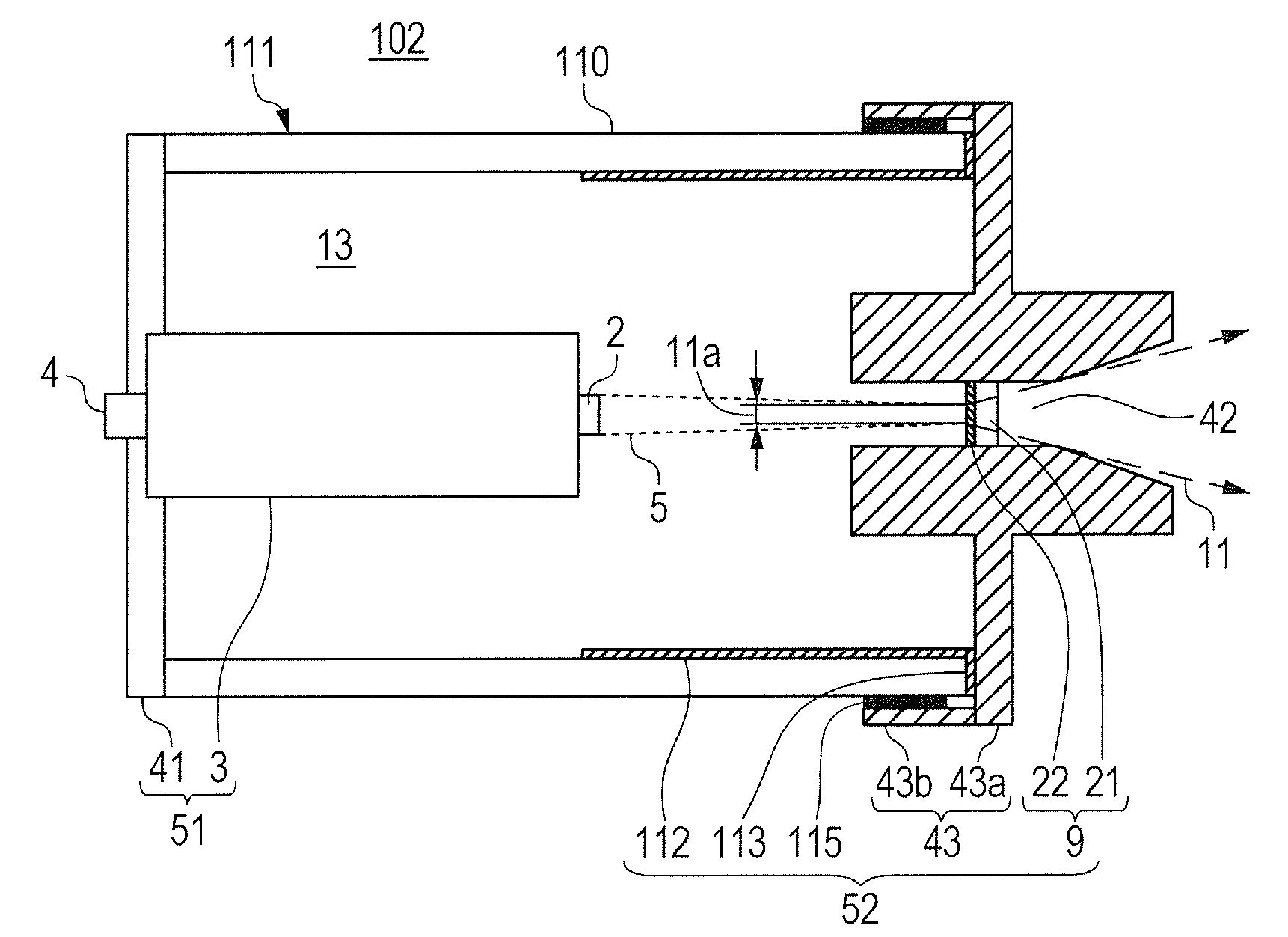
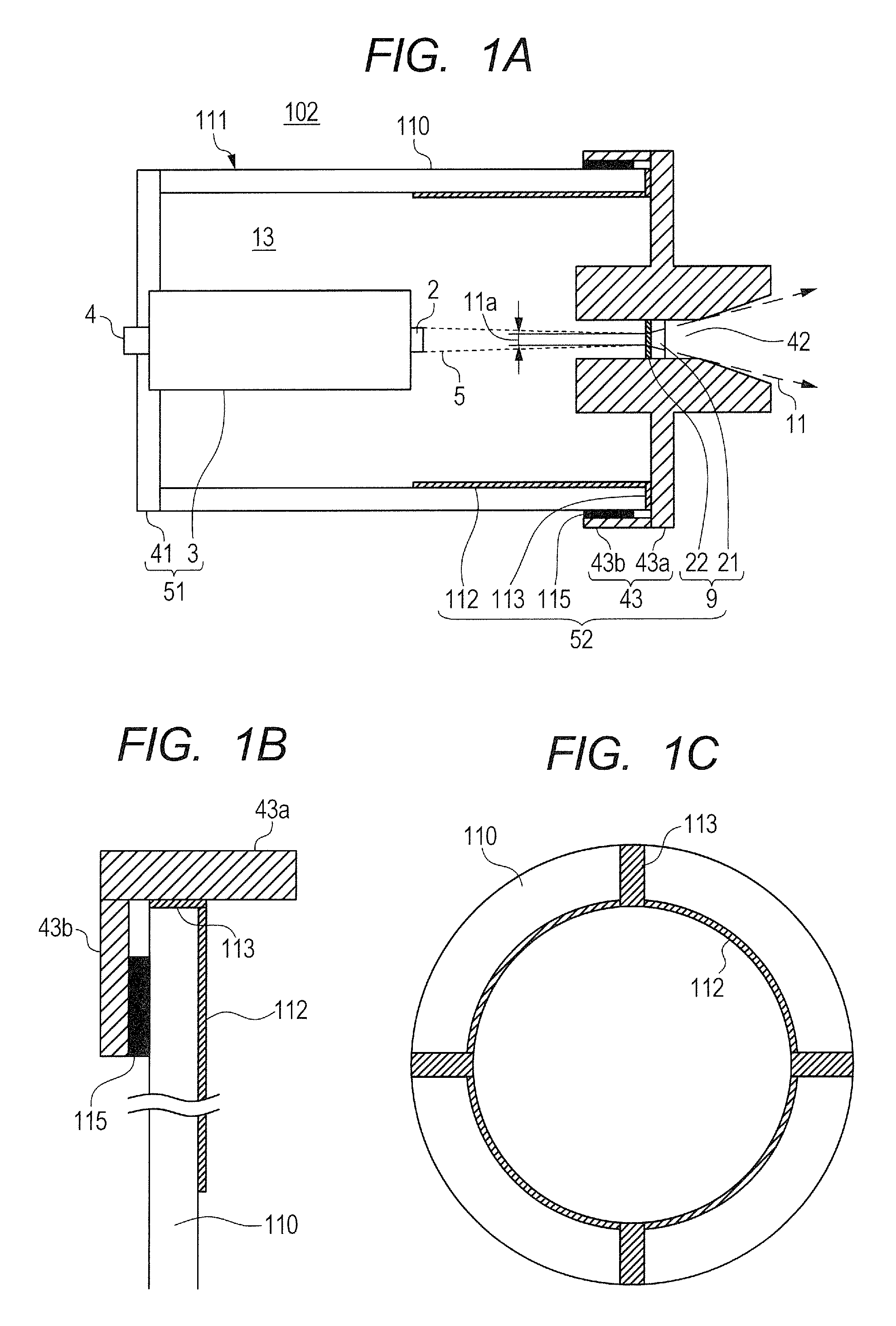
[0052]The X-ray generating tube 102 having the insulating tube 110 of FIG. 1A to FIG. 1C and the joining structure of FIG. 1A to FIG. 1C for joining the anode member 43 to the insulating tube 110 was manufactured and mounted to the X-ray generating apparatus 101.
[0053]As illustrated in FIG. 1B, the inner circumferential conductive film 112 was formed from a Ti—Cu-based material used as a ceramic metalizing material, on the inner circumferential surface of the insulating tube 110 that was made of alumina on the anode 52 side. As illustrated in FIG. 1C, the end surface conductive films 113 each having a width of 2 mm and continuous from the inner circumferential conductive film 112 were formed in four places on the end surface of the insulating tube 110 on the anode 52 side with use of the same material as the inner circumferential conductive film 112. The inner circumferential conductive film 112 and the end surface conductive films 113 were formed by preparing a paste that contained...
example 2
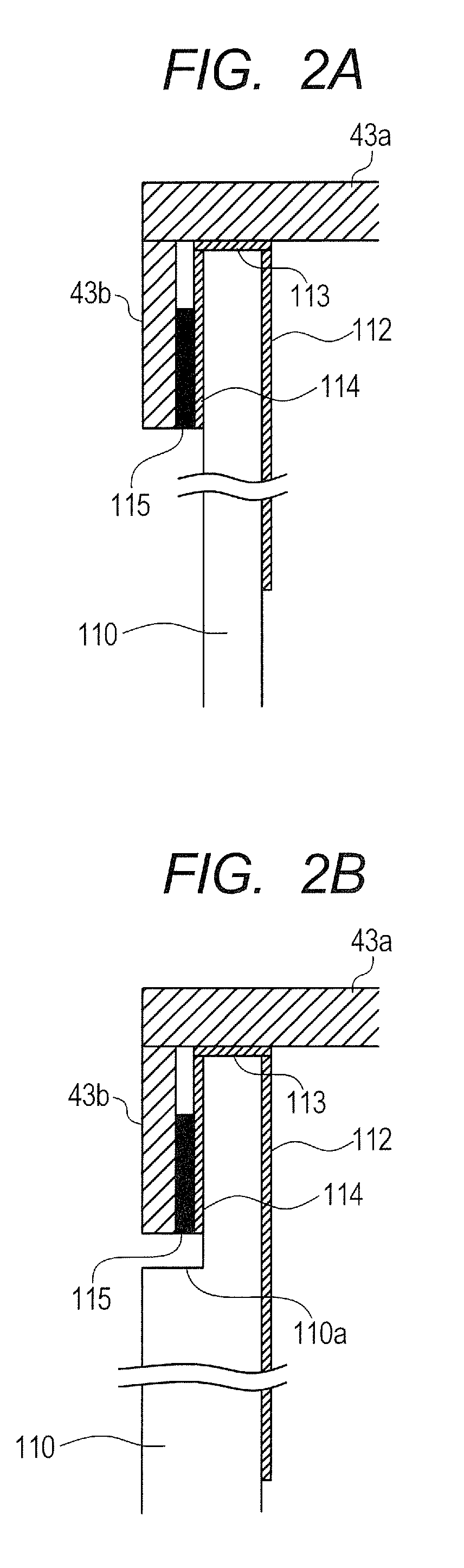
[0059]The X-ray generating tube 102 having the insulating tube 110 of FIG. 2B and the joining structure of FIG. 2B for joining the anode member 43 to the insulating tube 110 was manufactured and mounted to the X-ray generating apparatus 101.
[0060]As in Example 1, the inner circumferential conductive film 112 and the end surface conductive films 113 were formed from a Ti—Cu-based material, and the same material and the same method were used to form the outer circumferential conductive film 114 on the circumferential surface of the insulating tube 110 so as to be continuous from the end surface conductive films 113.
[0061]Next, a silver brazing filler metal wire was wound as the joining member 115 around the circumference of the insulating tube 110 in a part closer to the anode member 43 than the level difference 110a. Thereafter, components were arranged so as to bring the anode member 43 into contact with the end surface conductive films 113 formed on the insulating tube 110, and to ...
example 3
[0063]In Example 3, the X-ray generating apparatus 101 of Example 1 was used to construct the radiography system 60 of FIG. 4. The radiography system 60 of Example 3 in which the X-ray generating apparatus 101 reduced in changes in X-ray output was provided was successful in yielding an X-ray photographed image high in SN ratio.
[0064]According to the present invention, electrical connection is made between the inner circumferential conductive film and the anode member via the end surface conductive film, which is sandwiched between an end surface of the insulating tube at one end and the anode member and which is electrically connected to the anode member. This improves the reliability of electrical connection between the inner circumferential conductive film and the anode member, and prevents without fail the charging of the inner surface of the insulating tube, thereby providing an X-ray generating tube that is reduced in changes in X-ray output. In addition, an X-ray generating a...
PUM
 Abstract
Description
Claims
Application Information
 - R&D
- Intellectual Property
- Life Sciences
- Materials
- Tech Scout
- Unparalleled Data Quality
- Higher Quality Content
- 60% Fewer Hallucinations
Browse by: Latest US Patents, China's latest patents, Technical Efficacy Thesaurus, Application Domain, Technology Topic, Popular Technical Reports.
© 2025 PatSnap. All rights reserved.Legal|Privacy policy|Modern Slavery Act Transparency Statement|Sitemap|About US| Contact US: help@patsnap.com