System and method for measuring characteristics of cuttings and fluid front location during drilling operations with computer vision

a technology of computer vision and cuttings, applied in adaptive control, instruments, borehole/well accessories, etc., can solve the problems of difficult monitoring of cuttings from fluids using classical instruments, significant portion of rig activities and sensing problems remain difficult to measure, and the process of separating cuttings from fluids may be difficult to monitor using classical instruments, so as to save mud and increase efficiency

Active Publication Date: 2016-05-12
HELMERICH & PAYNE TECH LLC
View PDF14 Cites 135 Cited by
  • Summary
  • Abstract
  • Description
  • Claims
  • Application Information

AI Technical Summary

Benefits of technology

[0007]By applying automated, computer-based video interpretation, continuous, robust, and accurate assessment of many different phenomena can be achieved through pre-existing video data without requiring a person-in-the-loop. Automated interpretation of video data is known as computer vision, and recent advances in computer vision technologies have led to significantly improved performance across a wide range of video-based sensing tasks. Computer vision can be used to improve safety, reduce costs and improve efficiency.
[0008]As drilling fluid is pumped into the well-bore and back up, it typically carries with it solid material known as drilling cuttings. These cuttings are typically separated from the drilling fluid on an instrument known as a shale shaker or shaker table. The process of separating the cuttings from the fluid may be difficult to monitor using classical instrumentation due to the violent nature of the shaking process. Currently the volume of cuttings is difficult to measure and typically requires man-power to monitor. Knowledge of the total volume and / or approximate volume of the cuttings coming off the shaker table may improve the efficiency, safety, and / or environmental impact of the drilling process.
[0011]Therefore there is a need for an automated computer vision based technique for identifying cuttings on a belt, and estimating various features regarding their shape, size, volume and other parameters. Information from this system can be used to provide real-time information about the well-bore to the drill-team, flag unexpected changes in the particle sizes and shapes, and / or provide a long-term recording of the particle characteristics for post-drilling analyses.

Problems solved by technology

Despite the multitude of sensors on today's rigs, a significant portion of rig activities and sensing problems remain difficult to measure with classical instrumentation, and person-in-the-loop sensing is often utilized in place of automated sensing.
The process of separating the cuttings from the fluid may be difficult to monitor using classical instrumentation due to the violent nature of the shaking process.
Currently the volume of cuttings is difficult to measure and typically requires man-power to monitor.
Additionally, the location and orientation of the fluid front on the shale shaker is an important parameter to the drilling process that may be difficult to measure accurately.
Currently this is somewhat difficult to measure and requires man-power to monitor.
This process is time consuming, expensive, and error prone.
Classical instrumentation approaches to particle analysis are extremely difficult to design and implement—the sizes, shapes, and consistencies of cuttings prohibit most automated mechanical handling and measurement.

Method used


Image

  • System and method for measuring characteristics of cuttings and fluid front location during drilling operations with computer vision
  • System and method for measuring characteristics of cuttings and fluid front location during drilling operations with computer vision
  • System and method for measuring characteristics of cuttings and fluid front location during drilling operations with computer vision

Examples


Embodiment Construction

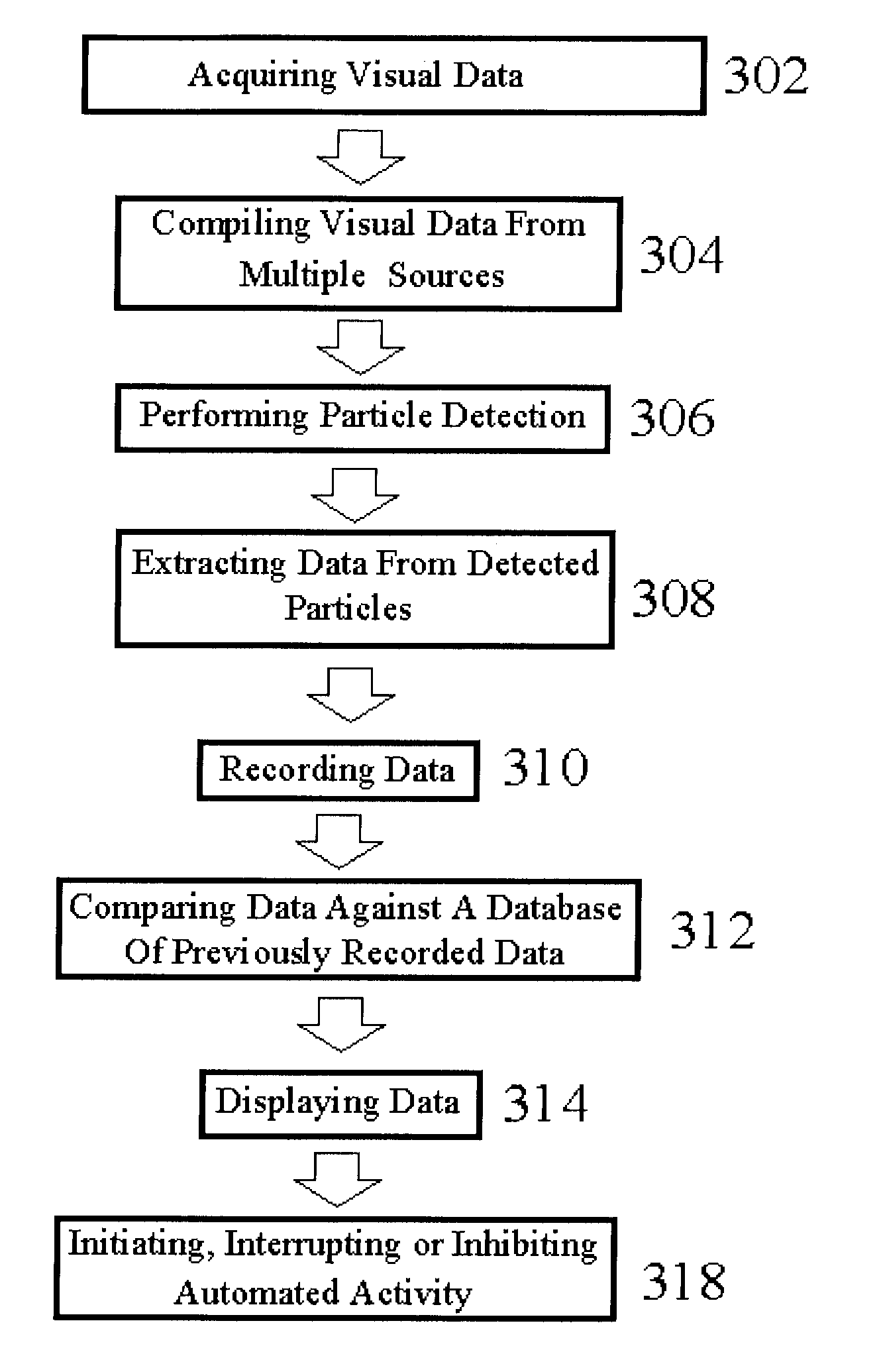
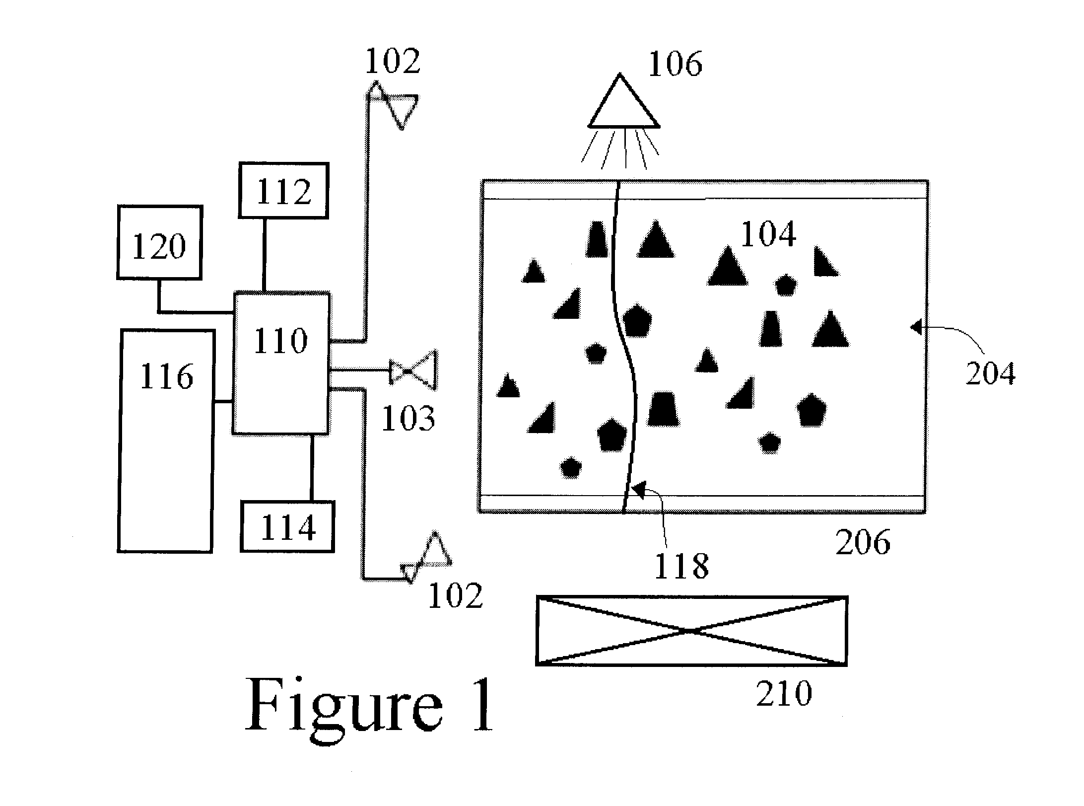
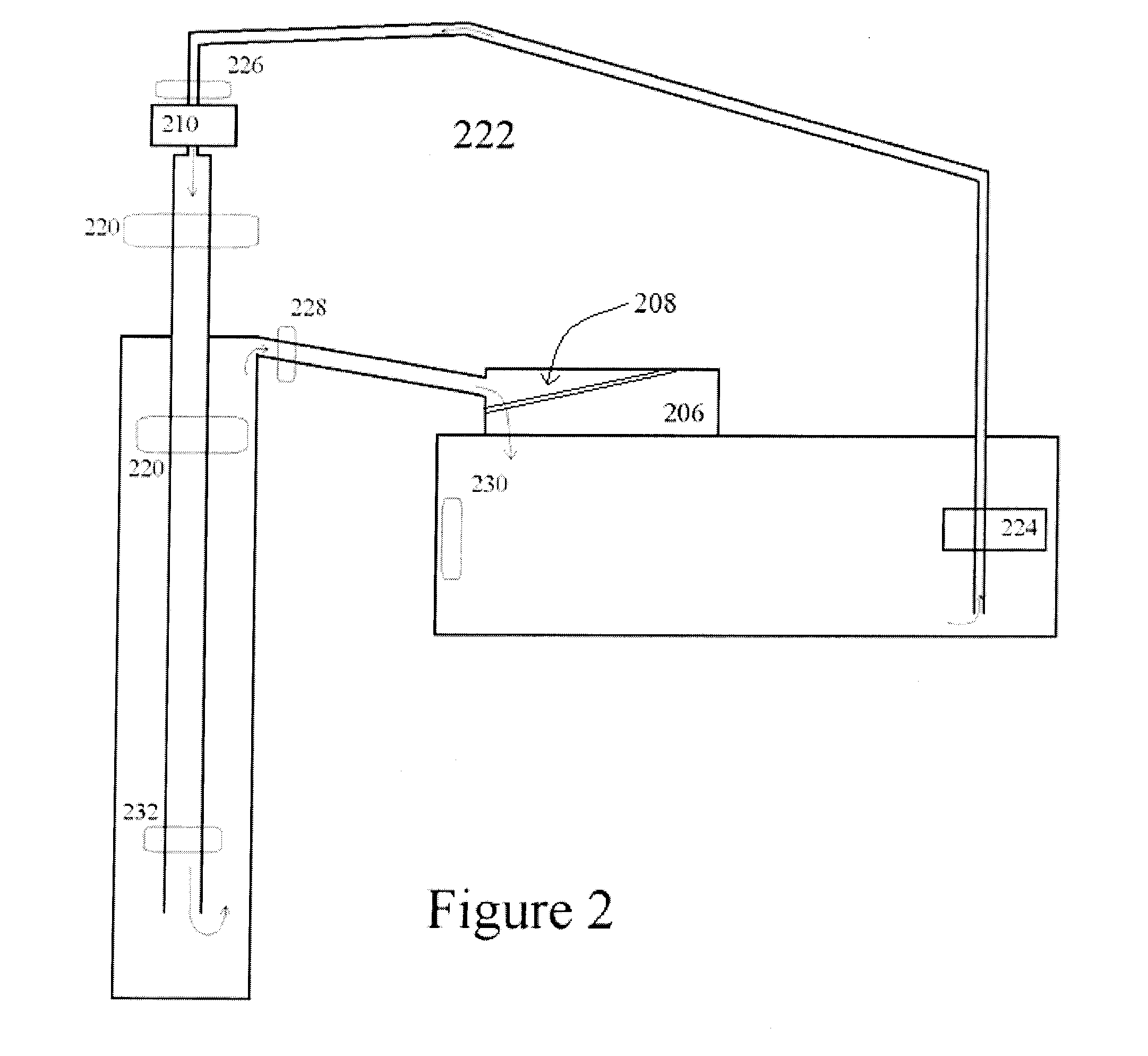
[0018]The disclosed method and system typically contains several parts including at least one camera 102 (video, or single-frame) oriented as to view a shaker table 206 on which the particulate matter passes and / or oriented to view the cuttings 104 as they approach and / or fall off the edge of a shaker table 206. The system and variations of the system may also include a belt 204, shaker table screen 208, machinery control system 116 and other drilling or industrial equipment 210. Cameras 102 may be oriented as to provide off-axis views (e.g., 90 degrees offset), or may be oriented in the same general direction, but spatially offset to provide stereo vision. In alternative embodiments, Red Green Blue-Depth (“RGB-D”) cameras, ranging cameras, and / or other distance-sensing technologies 103, such as Light Detection and Ranging (“LIDAR”), may be used in addition to, or in place of cameras 102.

[0019]Depending on the speed of the belt 204 and the rate at which particles 104 are moving, cam...


PUM


Abstract

The invention relates to a system and method of for measuring the characteristics and volume of drill cuttings. The system comprises at least one camera operably connected to a processor for recording characteristics of drill cutting particles wherein said processor is configured to perform particle detection, extract features of said particles, or both. The processor is typically configured to initiate, interrupt or inhibit an automated activity based on the particle characteristics. The method comprises acquiring visual data from at least one camera, performing particle detection using said data, extracting feature data of any detected particles, alerting an operator and / or initiating, interrupting, or inhibiting automated activity.

Description

CROSS REFERENCE TO RELATED APPLICATIONS[0001]This application claims the benefit of U.S. Provisional Application Serial No. 62 / 078,573 filed Nov. 12, 2014. Applicant incorporates by reference herein Application Ser. No. 62 / 078,573 in its entirety.[0002]This application additionally claims the benefit of U.S. Provisional Application Ser. No. 62 / 212,252 filed Aug. 31, 2015. Applicant incorporates by reference herein Application Ser. No. 62 / 212,252 in its entirety.[0003]This application additionally claims the benefit of U.S. Provisional Application Ser. No. 62 / 212,233 filed Aug. 31, 2015. Applicant incorporates by reference herein Application Ser. No. 62 / 212,233 in its entirety.FIELD OF THE INVENTION[0004]The invention relates to systems and methods for measuring characteristics and volume of cuttings during drilling operations and locating the fluid front on a shale shaker with computer vision.BACKGROUND AND SUMMARY[0005]Modern drilling involves scores of people and multiple inter-co...

Claims


Application Information

Patent Timeline
Patent Type & Authority Applications(United States)
IPC IPC(8): E21B44/00G05B15/02
CPCG05B15/02E21B44/00G01N15/0227G01N33/24E21B49/005E21B21/065E21B21/08
Inventor TORRIONE, PETER A.
Owner HELMERICH & PAYNE TECH LLC
Why Eureka
Try Eureka