System and method for a turbocharger driven coolant pump

a technology of turbocharger and coolant pump, which is applied in the direction of liquid fuel engines, machines/engines, mechanical equipment, etc., can solve the problems of increased potential for engine misfire, loss of torque and engine speed, incomplete combustion, etc., and achieves increased air density, increased power, and increased air temperature

Inactive Publication Date: 2016-05-12
FORD GLOBAL TECH LLC
View PDF5 Cites 6 Cited by
  • Summary
  • Abstract
  • Description
  • Claims
  • Application Information

AI Technical Summary

Benefits of technology

[0002]Turbocharged and supercharged engines may be configured to compress ambient air entering the engine in order to increase power. Because compression of the air may cause an increase in air temperature, a charge air cooler (CAC; also referred to as an intercooler) may be employed to cool the heated air, thereby increasing the density of the air and further increasing the potential power of the engine. In one example, the CAC may be a liquid-cooled CAC with coolant flowing through internal cooling tubes of the CAC. As such, a coolant pump coupled to the CAC may be required to control coolant flow through the CAC and thus local CAC cooling. CACs may be used to maintain the charge air at a temperature low enough to increase combustion stability but high enough to reduce condensate formation within the CAC.
[0006]As one example, the issues described above may be addressed by a method for adjusting a coolant flow through a charge air cooler with a single coolant pump based on turbocharger speed, the single coolant pump mechanically driven by rotative power from a turbocharger. In this way, operation of the single coolant pump is powered by rotative power from the turbocharger and operation of the single coolant pump is controlled by turbocharger speed, thereby reducing engine power consumption and control complexity of the engine.
[0007]For example, the coolant pump may be mechanically coupled to and thus driven by a rotating shaft of the turbocharger coupling a turbocharger compressor to a turbocharger turbine. As such, the coolant pump is powered by turbocharger speed and a speed of the coolant pump increases with increasing speed of the rotating shaft. The coolant pump may be disposed in a charge air cooling circuit including the charge air cooler (CAC), a low-temperature radiator, and a thermostat valve. As turbocharger speed increases, coolant flow through the CAC increases. Further, as turbocharger speed increases, charge air flow from the compressor and to the CAC also increases. In this way, the CAC may provide the required cooling to the increased charge air flow as turbocharger speed increases. As such, there is a positive, linear relationship between the rotational speeds of the rotating shaft of the turbocharger to which the coolant pump is mechanically coupled and the amount of heated charge air produced by the compressor. Moreover, the system of direct coupling of the coolant pump to the rotating shaft of the turbocharger eliminates the need for additional electrical system (e.g., electrical, battery or engine-driven component) to drive the charge air cooling circuit. As a result, engine control complexity and power consumption may be reduced.

Problems solved by technology

However, if overcooling by the CAC occurs, condensation (e.g., water droplets) may form on any internal surface of the CAC that is cooler than the dew point of the compressed air.
During transient conditions, such as hard vehicle acceleration, these water droplets may be blown out of the CAC and into the combustion chambers of the engine resulting in increased potential for engine misfire, loss of torque and engine speed, and incomplete combustion, for example.
However, this configuration requires additional circuits and energy to drive the coolant pump.
Thus, there is added complexity, energy consumption and packaging burdens of said system.
As a result, there may be a rise in the cost of manufacturing and overall reduction in fuel economy.

Method used


Image

  • System and method for a turbocharger driven coolant pump
  • System and method for a turbocharger driven coolant pump
  • System and method for a turbocharger driven coolant pump

Examples


Embodiment Construction

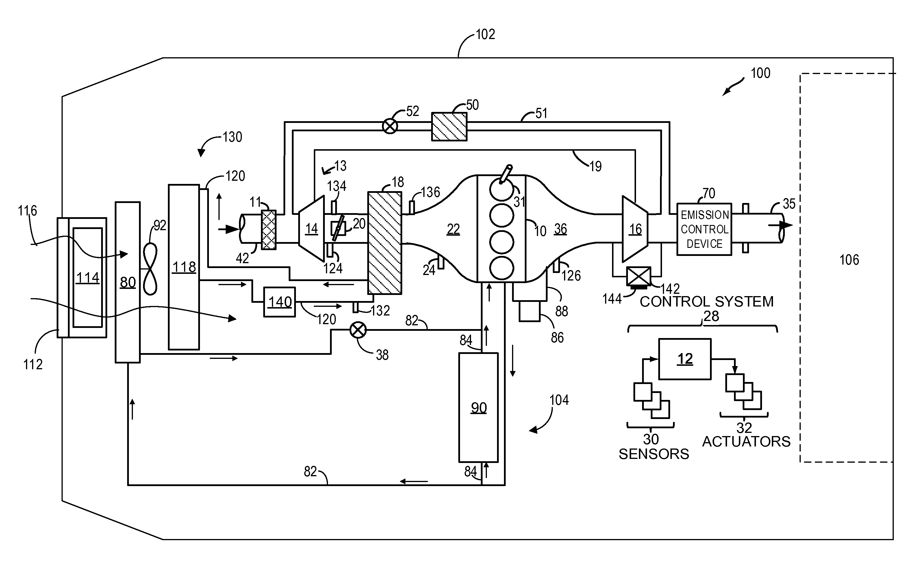
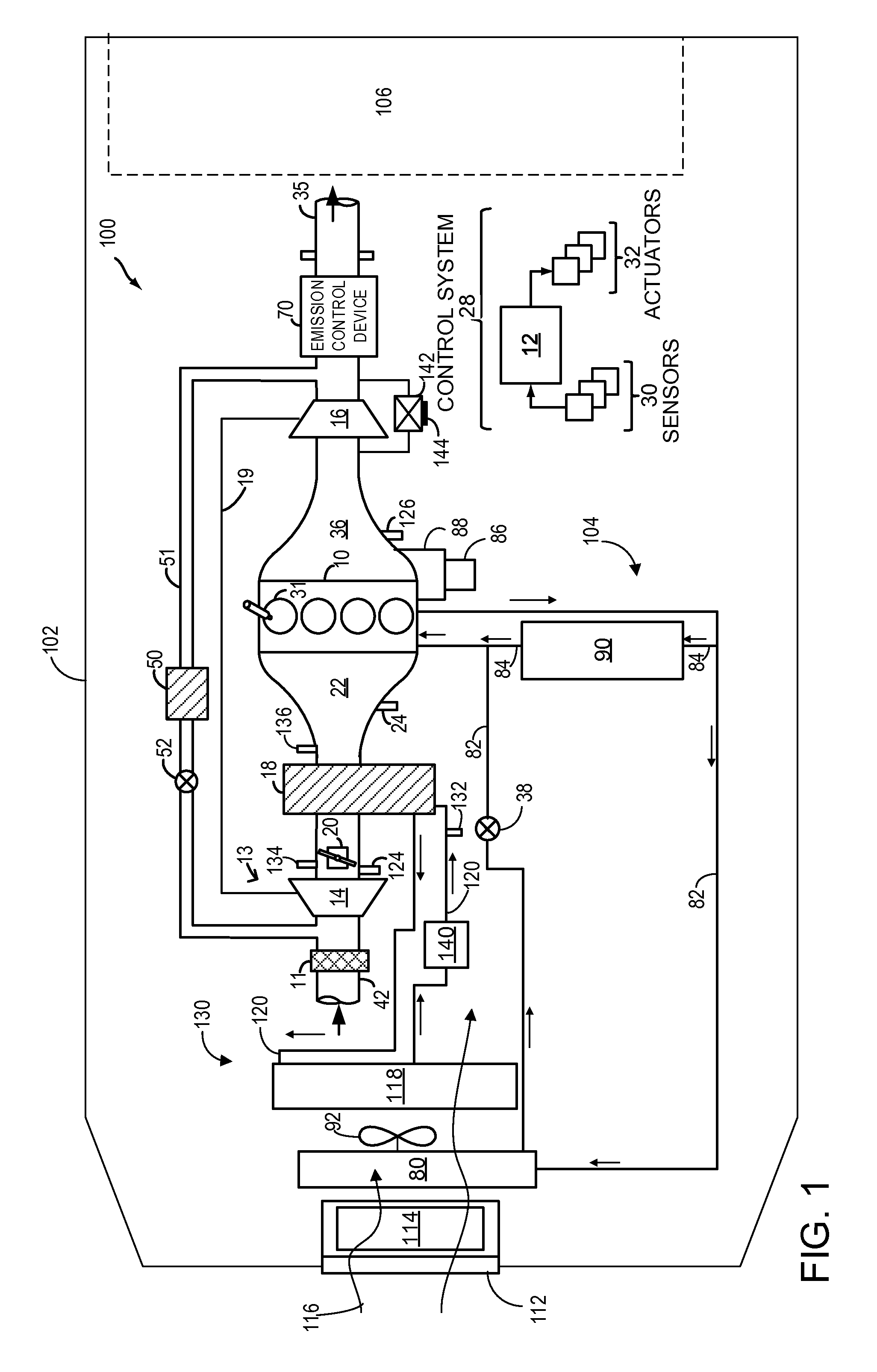
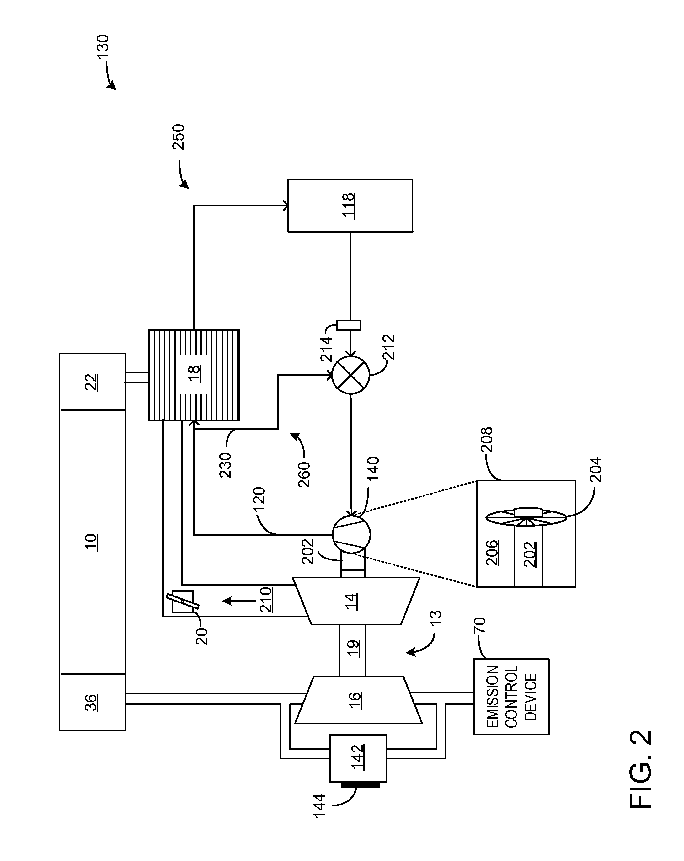
[0013]The following description relates to methods and a system for powering a coolant pump to drive a coolant using exhaust gas-driven rotations of a turbocharger. In one example, a coolant pump having an impeller is operably coupled to a rotating shaft extending axially from a compressor side of the turbocharger. As the rotating shaft spins in response to the flow of exhaust gases, the impeller may simultaneously spin, thereby powering the coolant pump to drive coolant into a circuit, such as a charge air cooling circuit, without an additional engine-driven or electrical coolant pump or power source. Thus, charge air cooling may be provided by a CAC in an engine system, such as the engine system shown in FIG. 1. The CAC may be a water-to-air CAC which cools the charge air with internally circulating coolant pumped by a single coolant pump. FIG. 2 illustrates another example of an embodiment of the system, comprising the charge air cooling circuit with a coolant pump coupled to the...


PUM


Abstract

Methods and a system are provided for powering a coolant pump to drive a coolant flow through a charge air cooler using exhaust gas-driven rotations of a turbocharger. In one example, a method may include adjusting a coolant flow through a charge air cooler with a coolant pump, the coolant pump mechanically driven by rotative power from a turbocharger. As such, coolant flow may increase with increasing turbocharger speed and the method may further include adjusting a wastegate of a turbocharger turbine to adjust power provided to the coolant pump.

Description

FIELD OF THE INVENTION[0001]The field of the invention relates generally to a charge air cooler coolant circuit for an internal combustion engine.BACKGROUND AND SUMMARY[0002]Turbocharged and supercharged engines may be configured to compress ambient air entering the engine in order to increase power. Because compression of the air may cause an increase in air temperature, a charge air cooler (CAC; also referred to as an intercooler) may be employed to cool the heated air, thereby increasing the density of the air and further increasing the potential power of the engine. In one example, the CAC may be a liquid-cooled CAC with coolant flowing through internal cooling tubes of the CAC. As such, a coolant pump coupled to the CAC may be required to control coolant flow through the CAC and thus local CAC cooling. CACs may be used to maintain the charge air at a temperature low enough to increase combustion stability but high enough to reduce condensate formation within the CAC.[0003]Howev...

Claims


Application Information

Patent Timeline
Patent Type & Authority Applications(United States)
IPC IPC(8): F01P5/04F01P7/04F02B37/16F04D29/26F04D25/04F02B33/40F01P3/00F01P7/02
CPCF04D29/26F04D25/04F02B33/40F01P7/026F01P5/04F01P3/00F01P7/046F02B37/164F01P5/12F01P7/164F01P2060/12F02B29/0443F02B37/18F01P2060/02F02B29/04F02B29/0493F04D13/04Y02T10/12F01P3/20F01P11/04F01P11/06F01P2007/146
Inventor MEHRAVARAN, MEISAMWADE, ROBERT ANDREW
Owner FORD GLOBAL TECH LLC
Why Eureka
Try Eureka