
Sintered bearing and method of manufacturing same

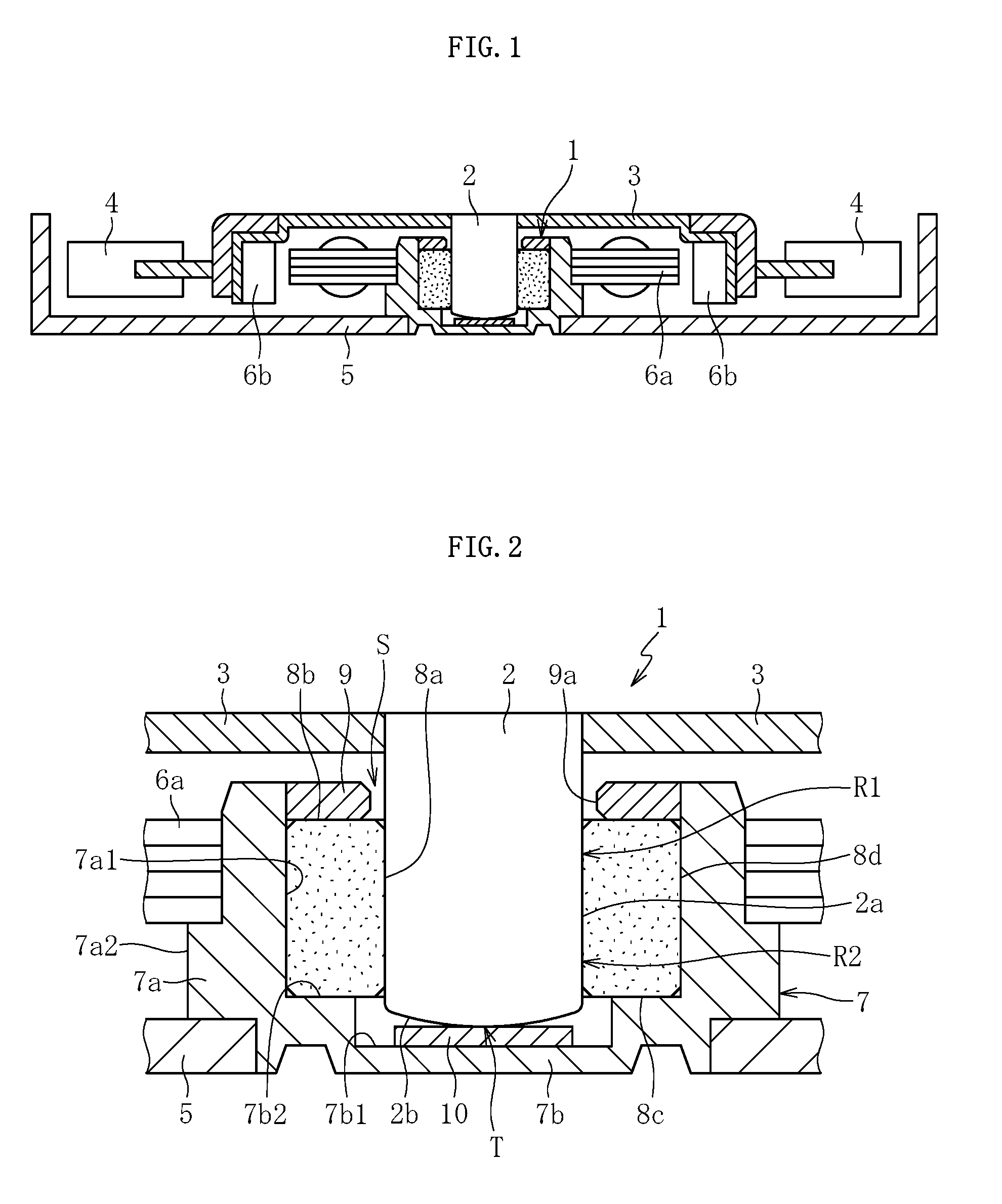
a technology bearings, which is applied in the direction of sliding contact bearings, mechanical equipment, transportation and packaging, etc., can solve the problems of increased manufacturing costs owing to increased man-hours, inability to obtain desired bearing stiffness, etc., to achieve the effect of reducing the opening of the surface, increasing the flowability of metal powder mixture, and reducing the opening

Active Publication Date: 2016-05-19
NTN CORP
View PDF16 Cites 3 Cited by
  • Summary
  • Abstract
  • Description
  • Claims
  • Application Information

AI Technical Summary

Benefits of technology

The present invention relates to a method for making a sintered bearing. By using a fine metal powder mixture with high-circularity electrolytic copper powder, the density of the sintered bearing is increased, while surface openings are reduced. This results in a more uniform pore structure in the bearing, which improves stiffness without compromising dynamic pressure absence. The metal powder mixture can be more easily filled into the forming die, leading to more uniform and fine inner pores. These technical effects improve the overall performance of the sintered bearing.

Problems solved by technology

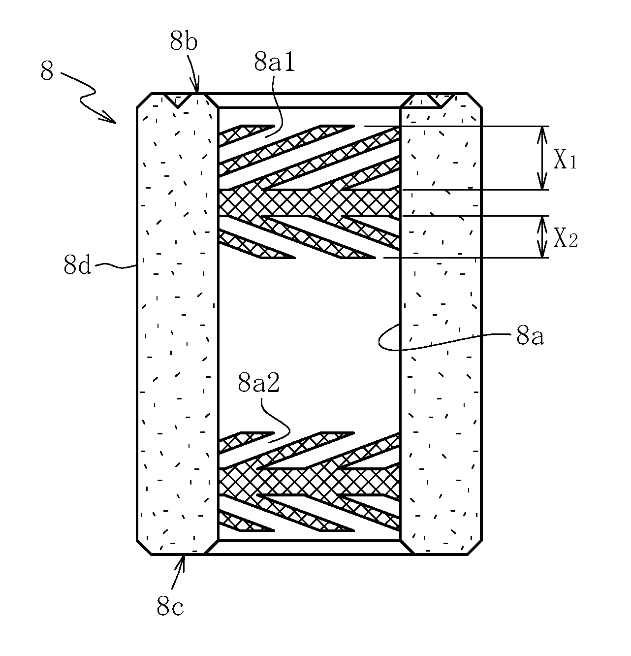
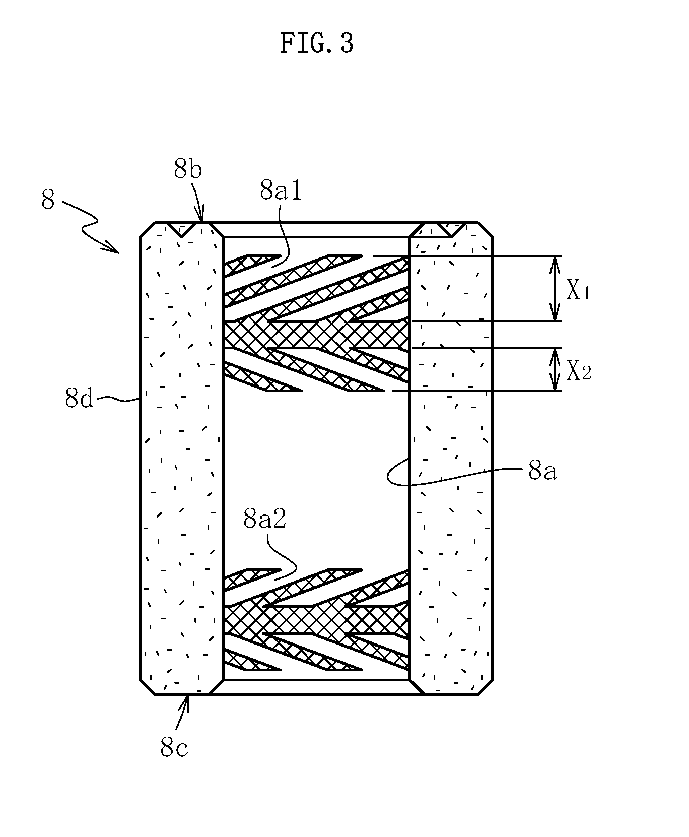
However, the sintered bearing has an infinite number of pores opened in a bearing surface, and hence there is risk in that the oil film in the sliding part is released from openings of the bearing surface to an inside of the sintered bearing, that is, so-called dynamic pressure absence occurs, with the result that desired bearing stiffness may not be obtained.
However, in this case, manufacturing cost increases owing to an increase in man-hour.

Method used


Image

  • Sintered bearing and method of manufacturing same
  • Sintered bearing and method of manufacturing same
  • Sintered bearing and method of manufacturing same

Examples


example 1

[0048]In order to confirm the effects of the present invention, the following test was conducted. First, an implementation product and a comparative product each having compositions shown in Table 1 were formed. The implementation product and the comparative product each have a cylindrical shape having an inner diameter of 1.5 mm, an outer diameter of 3.0 mm, and an axial dimension of 3.0 mm.

TABLE 1ImplementationComparativeproductproductCopper (wt %)Copper powder A57.8(electrolytic powder)Copper powder B40.5(electrolytic powder)Copper powder C17.3(atomized powder)Iron (wt %)Iron powder A39.913.3(reduced powder)Iron powder B26.6(atomized powder)Tin (wt %)Tin powder A1.5(atomized powder)Tin powder B1.5(atomized powder)Others0.80.8

[0049]Table 2 shows a particle size distribution and a circularity distribution of the copper powder A (electrolytic powder) and the copper powder B (electrolytic powder) in Table 1.

TABLE 2Copper powder ACopper powder BApparent density (g / cm3)1.40-1.701.35-1....


PUM

PropertyMeasurementUnit
particle diameteraaaaaaaaaa
apparent densityaaaaaaaaaa

Abstract

A sintered bearing includes a sintered metal formed by using a metal powder mixture containing copper powder and iron powder. The metal powder mixture contains 80 wt % or more of particles having an average particle diameter of less than 45 μm. The copper powder contains electrolytic copper powder. The electrolytic copper powder contains 40 number % or more of particles having a circularity of 0.64 or more.

Description

TECHNICAL FIELD[0001]The present invention relates to a sintered bearing, and more particularly, to a sintered bearing formed by using a metal powder mixture containing copper powder and iron powder and a manufacturing method for the sintered bearing.BACKGROUND ART[0002]A sintered bearing is used under a state in which inner pores are impregnated with a lubricating oil, and along with rotation of the sintered bearing relative to a shaft to be supported, the lubricating oil impregnating an inner portion exudes to a sliding part between the sintered bearing and the shaft, to thereby form an oil film through which the shaft is rotatably supported. Such a sintered bearing has been used as a bearing configured to rotatably support a small motor such as an HDD, an LBP polygon scanner motor, or a fan motor due to the high rotation accuracy and quietness thereof.[0003]As the electronic device described above becomes thinner, the axial dimension of the sintered bearing is decreasing more and...

Claims


Application Information

Patent Timeline
Patent Type & Authority Applications(United States)
IPC IPC(8): F16C33/14B22F3/16H02K7/08C22C9/00F16C32/06F16C33/10B22F1/00B22F5/00B22F1/052
CPCF16C33/145B22F1/0003B22F3/16B22F5/00C22C9/00B22F2301/30F16C33/104H02K7/08B22F2301/10B22F2301/35F16C32/0633C22C1/0425F16C2370/12F16C2204/10F16C33/128C22C9/02F16C17/08F16C17/102B22F1/052B22F1/09
Inventor KURIMURA, TETSUYAITO, FUYUKIKOMATSUBARA, SHINJIUCHIYAMA, TADAHIRO
Owner NTN CORP
Learn More