Light transmitting electrically conductive member and method for patterning the same

a technology of electrically conductive components and light-emitting components, which is applied in the direction of electronic switching, pulse technique, instruments, etc., can solve the problems of remarkable difference in optical characteristics, degraded optical characteristics of the region which is required to be non-electrically conductive, and disadvantageous weak metal oxide types, etc., to achieve the effect of reducing haze in the non-electrically conductive region, increasing surface resistivity, and small amount of silver iodid

Active Publication Date: 2016-05-19
ALPS ALPINE CO LTD
View PDF3 Cites 11 Cited by
  • Summary
  • Abstract
  • Description
  • Claims
  • Application Information

AI Technical Summary

Benefits of technology

[0012]In the disclosed light transmitting electrically conductive member, when the silver nanowires in the non-electrically conductive region are transformed into a silver iodide, the surface resistivity can be increased as compared to that of the electrically conductive region without significantly changing the light transmittance from that of the electrically conductive region. In the non-electrically conductive region, the silver iodide is not present on the surface of the overcoat layer, or even if the silver iodide is present thereon, the amount of the silver iodide is very small; hence, a white cloudy silver iodide is hardly present on the surface of the non-electrically conductive region, the haze in the non-electrically conductive region is reduced, and as a result, the transparency thereof can be maintained high.

Problems solved by technology

However, this type of metal oxide is disadvantageously weak against a bending stress.
However, after the patterning is performed, there has been a problem in that between an electrically conductive region in which the electrically conductive nanowires remain and the non-electrically conductive region from which the electrically conductive nanowires are removed, a remarkable difference in optical characteristics is generated.
Hence, when an oxidizing agent is applied to a region which is required to be non-electrically conductive, the nanowires exposed to the surface of the electrically conductive layer are formed into a metal oxide compound and remain in the form of a white cloudy material, and as a result, a problem in that the optical characteristics of the region which is required to be non-electrically conductive are degraded may arise.
However, those oxidizing agents each have not an adequate degree of permeation into an overcoat layer, which is a resin layer, in which a network of silver nanowires is embedded, and hence, patterning to partition the electrically conductive region from the non-electrically conductive region is difficult to be precisely controlled.
In addition, when a lead layer is formed on the electrically conductive layer containing silver nanowires using a metal layer of copper or silver, a problem may arise in that this metal layer is liable to be damaged.

Method used


Image

  • Light transmitting electrically conductive member and method for patterning the same
  • Light transmitting electrically conductive member and method for patterning the same
  • Light transmitting electrically conductive member and method for patterning the same

Examples


example

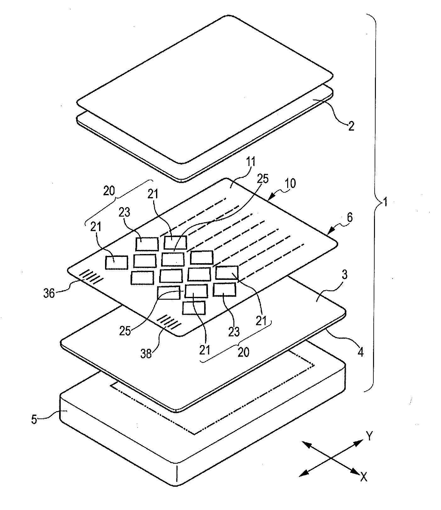
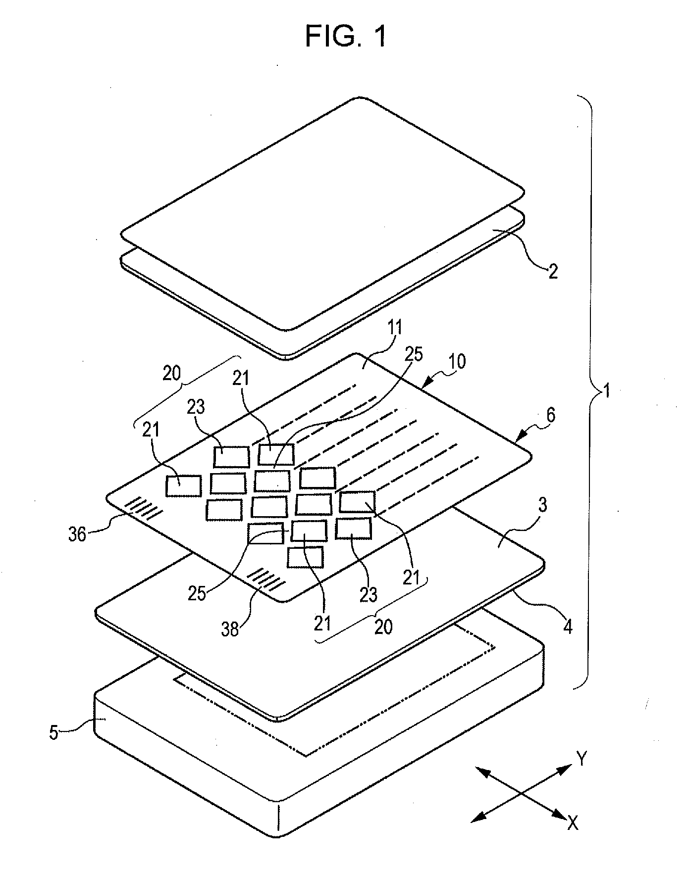
[0054]By the use of a light transmitting electrically conductive member 10 in which an electrically conductive layer 12 formed of a silver nanowire network 13 and an acrylic-based overcoat layer 14 and having a thickness of approximately 100 nm was formed on a surface of a PET film, as shown in FIG. 6, an electrically conductive region and a non-electrically conductive region were patterned.

[0055]In an iodizing treatment of the silver nanowires, dipping was performed for 120 seconds in an iodine-potassium iodine solution containing 0.1 percent by mass of iodine and 0.5 percent by mass of potassium iodine. In a removal treatment of a metal compound, such as a silver iodide, remaining on the surface of the overcoat layer 14, dipping was performed for 30 seconds in a sodium thiosulfate solution at a concentration of 10 percent by mass.


PUM

PropertyMeasurementUnit
total light transmittanceaaaaaaaaaa
thicknessaaaaaaaaaa
thicknessaaaaaaaaaa

Abstract

A method for patterning a light transmitting electrically conductive member uses a light transmitting laminate material in which an electrically conductive layer including an overcoat layer and silver nanowires embedded therein is formed on a surface of a light transmitting base film and includes a step of treating a surface of the electrically conductive layer which is not covered with a resist layer using an iodine solution to at least partially iodize the silver nanowires and a step of applying a thiosulfate solution to the surface of the electrically conductive layer which is not covered with the resist layer to remove a silver iodide exposed to a surface of the overcoat layer. Since a white cloudy or a whitened silver iodide is removed, the optical transmission characteristics of the non-electrically conductive region can be improved.

Description

CLAIM OF PRIORITY[0001]This application is a Continuation of International Application No. PCT / JP2014 / 068813 filed on Jul. 15, 2014, which claims benefit of Japanese Patent Application No. 2013-162020 filed on Aug. 5, 2013. The entire contents of each application noted above are hereby incorporated by reference.BACKGROUND[0002]1. Field of the Disclosure[0003]The present disclosure relates to a light transmitting electrically conductive member and a method for patterning the same.[0004]2. Description of the Related Art[0005]A light transmitting electrically conductive member disposed at a front side of a display panel has been used as an electrostatic touch panel or the like.[0006]In a related art light transmitting electrically conductive member, a light transmitting electrode layer is formed on a surface of a base material from indium tin oxide (ITO). However, this type of metal oxide is disadvantageously weak against a bending stress. In Japanese Unexamined Patent Application Publ...

Claims


Application Information

Patent Timeline
Patent Type & Authority Applications(United States)
IPC IPC(8): G06F3/044H03K17/96G06F3/041
CPCG06F3/044G06F2203/04112H03K17/962G06F3/0412G06F3/0446H01B1/22G06F3/041G06F2203/04103
Inventor YAMAI, TOMOYUKIBITO, MITSUOKITAMURA, YASUYUKI
Owner ALPS ALPINE CO LTD
Why Eureka
Try Eureka