
Apparatus and Corneal Remodeling Methods to Improve Vision in Macular Disease

a corneal and macular disease technology, applied in the field of corneal remodeling and applicator remodeling, can solve the problems of no known cause or effective treatment of dry amd, progressive loss of central vision, and loss of function, and achieve the effect of improving vision and being easy to remov

Inactive Publication Date: 2016-05-26
OPTIMAL ACUITY
View PDF1 Cites 3 Cited by
  • Summary
  • Abstract
  • Description
  • Claims
  • Application Information

AI Technical Summary

Benefits of technology

This patent describes methods for improving the vision of people with macular disease, which involves creating a more convex altered corneal topography to increase optical aberrations in a way that stimulates the remaining parts of the retina. The methods include using a femtosecond laser to create an off center pocket in the cornea, a thermal laser to create a pattern of corneal collagen shrinkage, and a thermal conducting wire to create collagen shrinkage in a similar pattern. These methods are temporary and can be repeated in different locations as the retinal disease progresses. The technical effects of the patent include improving vision in people with macular disease and providing temporary treatments for those with advanced disease.

Problems solved by technology

AMD causes progressive loss of central vision and therefore loss of the ability to function as one would desire in society for 15 million Americans.
There is no known cause or effective treatment for the dry type of AMD.
Unfortunately, the concomitant loss of peripheral vision with telescopes make such methods problematic.
Again, severe loss of peripheral vision and extreme cost and complexity make them impractical.
The eye, like any other optical system, suffers from a number of optical aberrations which reduce vision.
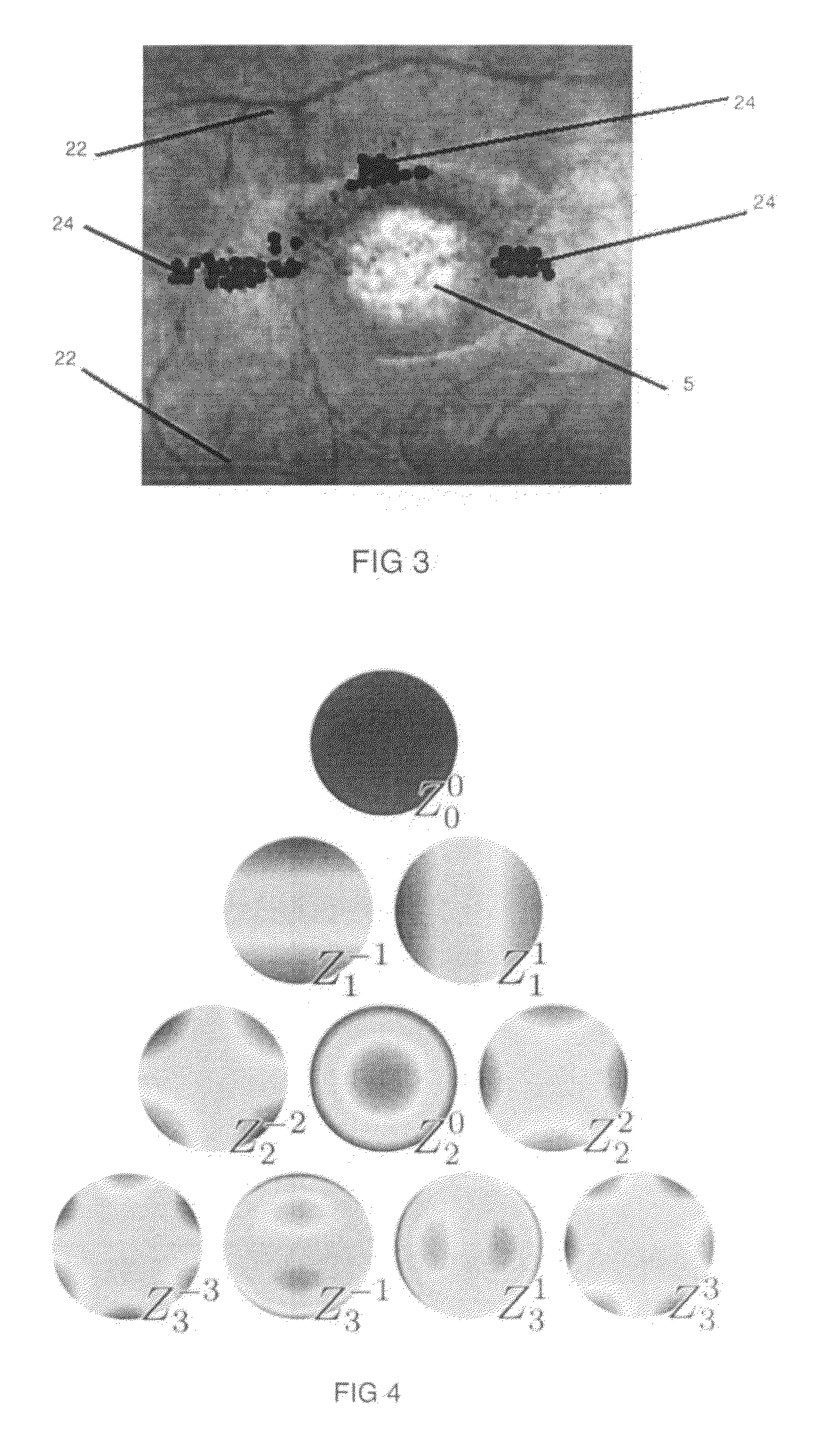
None of these techniques effectively correct the higher order aberrations of spherical aberration, coma and trefoil which fortunately do not often occur naturally.
Ophthalmologists, optometrists and opticians exist because no eye is ideal.
If one skilled in the art were to follow each of the exemplary techniques and methods of the prior art in this field, they would not be able to improve the vision in a person with a macular disease which has destroyed foveal function.
In fact, all operative guidelines as well as the labeling guidelines of the FDA forbid the use of such lasers and techniques in patients with retinal disease as being contraindicated (if not pointless).
First, the prior art alters the corneal shape permanently by removing corneal tissue with excimer laser ablation, when in fact macular diseases are progressive, wherein available locations are likely to change over time.

Method used


Image

  • Apparatus and Corneal Remodeling Methods to Improve Vision in Macular Disease
  • Apparatus and Corneal Remodeling Methods to Improve Vision in Macular Disease
  • Apparatus and Corneal Remodeling Methods to Improve Vision in Macular Disease

Examples


example 1

[0049]A patient with macular degeneration and best corrected vision of 20 / 400 in the right eye with no reading vision (less than Jaeger 10 meaning he could not read even the largest print) underwent a four spot treatment with a thulium laser at a power of 46 millijoules per spot. The four spots were equidistant from each other at the corners of a square 6 mm×6 mm in size. Rather than centering the square with the pupil in the center, it was decentered laterally on the cornea by 4 mm as shown in FIG. 6c. The iTrace showing the pre and post operative retinal spot diagram shows the ray tracing pattern of light from the image upon the retina is seen in FIG. 7. The grid in the figure is 1 mm×1 mm of the patient's retina centered on the fovea. Each box represents 10 arc minutes or 0.16 mm of the retina. It should be noted that the typical fovea is only 0.3 mm in diameter so that any ray tracings outside of the central 4 boxes is outside the fovea where PRLs may exist. The preoperative tra...

example 2

[0050]A female patient with early AMD had best corrected vision of 20 / 200 but could read only Jaeger 10 size print. She underwent the exact same procedure as in Example 1. Her ray tracings are shown in FIG. 8. Her preoperative image on the left side of FIG. 8 subtended only 0.1 mm×0.16 mm precisely on her fovea. It appears smaller than the preoperative image of Example 1 because he had preoperative myopia and optical aberrations of 0.45 microns which spread the image out. Her preoperative total optical aberrations were only 0.12 microns which included astigmatism of 0.1 microns, coma of 0.01 microns and trefoil of 0.01 microns and no contribution from myopia or hyperopia. Post operatively, her ray tracing on the right of FIG. 8 had expanded to 0.3 mm×0.3 mm and had spread both vertically and horizontally to just beyond the edge of the fovea, where the potential acuity is almost as good as in the fovea. She did indeed achieve her potential acuity, improving to 20 / 50 vision and Jaeger...

example 3

[0051]In this woman with geographic atrophy of the macula which had destroyed her fovea and much of the macula, only a PRL more than 0.5 mm above the fovea could be detected by preoperative microperimetry (Centerview Inc, San Jose, Calif.). In order to spread the image that far above the fovea, a 4 spot pattern with the thulium laser using 48 mJ of power was decentered such that one spot was directly on the visual axis, upon the pupil center as shown in FIG. 6d. The preoperative best corrected vision was 20 / 800 and near vision was less than Jaeger 10. The post operative vision improved to 20 / 200 and she could read Jaeger 8 size print. The ray tracing in FIG. 9 explains this dramatic improvement. Pre operatively the image subtended 0.2 mm in the fovea of the retina as seen on the left side of FIG. 9, while post operatively it had spread to 0.6 mm×0.8 mm in size, with the image hitting her PRL between 0.5 and 0.6 mm above her fovea. This was accomplished by increasing her total optica...


PUM


Abstract

Apparatus and methods to improve the vision in a person with a macular disease, comprising the purposeful temporary creation of increased corneal optical aberrations. Strategies include corneal treatment patterns that are one or more of asymmetric, decentered or eccentric with respect to the visual axis, which would result in worsening vision in a normal eye but surprisingly become sight enhancing in a patient with the loss of foveal function due to macular disease.

Description

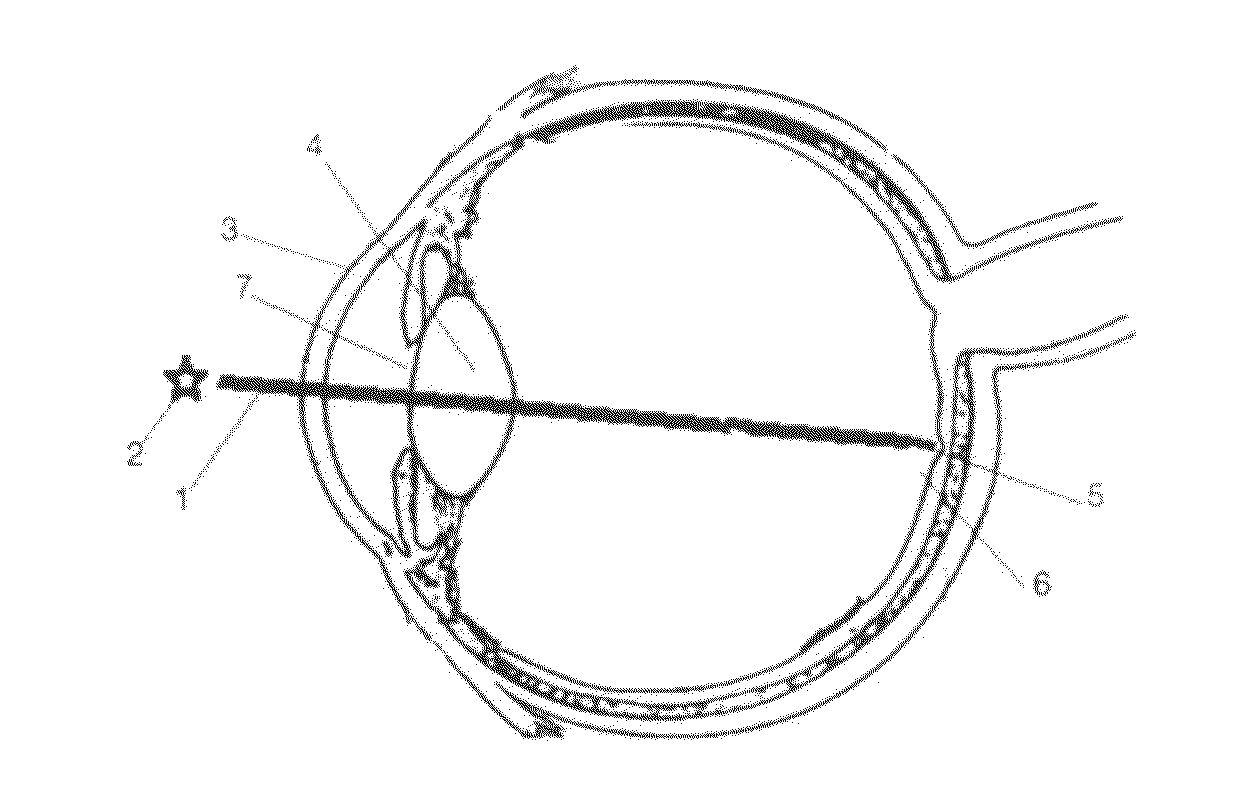
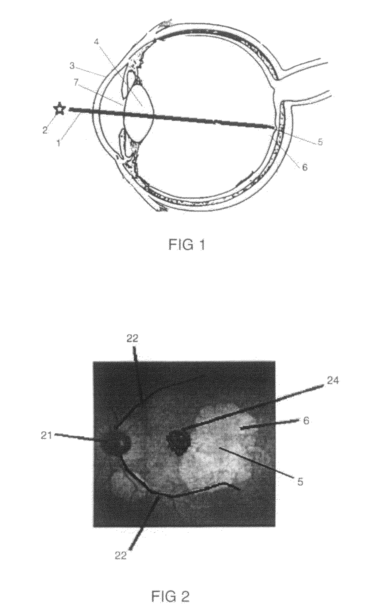
CROSS REFERENCE TO RELATED APPLICATION[0001]The present application claims priority to co-pending U.S. provisional patent application No. 62 / 083,656 filed Nov. 24, 2014, and entitled “APPARATUS AND CORNEAL REMODELING METHOD TO IMPROVE VISION IN MACULAR DISEASE”, the entire contents of which is incorporated by reference herein.FIELD OF THE INVENTION[0002]The present invention relates to apparatus and laser means to alter the shape of the human cornea in order to improve the vision in a person with macular disease.BACKGROUND OF THE INVENTION[0003]The retina is the light sensitive portion at the back of the human eye which receives light rays focused by the cornea and lens at the front of the eye. In a normal eye (FIG. 1) light is reflected from an object (2) and is focused by the cornea (3) and lens (4) to the 0.5 mm diameter circular fovea (5) of the retina, the area of maximal visual acuity. The fovea is at the center of a 5 mm diameter circular retinal area called the macula (6). T...

Claims


Application Information

Patent Timeline
IPC IPC(8): A61F9/008A61B18/08A61B18/14
CPCA61F9/00827A61B18/14A61F9/00834A61F9/0084A61F2009/00885A61B2018/144A61B2018/00994A61F2009/00872A61B18/082
Inventor YAVITZ, EDWARD ALLEN
Owner OPTIMAL ACUITY
Learn More