Prepreg for manufacturing composite materials

a composite material and pre-prep technology, applied in the direction of synthetic resin layered products, other domestic articles, coatings, etc., can solve the problems of significantly reducing the mechanical properties of the composite material, air can be trapped, inter-ply voids can exist, etc., to improve the fracture toughness, improve particle dispersion, and improve the effect of mechanical properties

Inactive Publication Date: 2016-06-09
GURIT (UK) LTD
View PDF4 Cites 20 Cited by
  • Summary
  • Abstract
  • Description
  • Claims
  • Application Information

AI Technical Summary

Benefits of technology

[0043]The present invention is predicated on the finding by the present inventors that a prepreg, which may be a fully impregnated prepreg, can be provided with a combination of bulk and surface properties, in particular high drape and low surface tack, which can provide enhanced air removal from a stack of prepregs. The result is a prepreg which can provide even lower void content in the resulting cured fibre reinforced resin matrix composite materials. The prepreg can readily be handled, due to low surface tack, and laid up into three dimensionally profiled moulds, due to high drape. The prepreg has particular application for the manufacture of an elongate structural member, such as a spar or beam, most particularly a sparcap for a wind turbine blade.
[0084]In accordance with this aspect of the invention, by providing the toughening particles only in the interlaminar regions of the composite material, the toughness is increased with minimal reduction of stiffness related properties. In addition, material cost is reduced, because a lower net amount of toughener additive is used, and resin viscosity remains unchanged.

Problems solved by technology

However, one particular problem with fully impregnated prepregs is that when a stack of such prepregs is formed, air can be trapped between the adjacent prepreg plies, with the result that in the final cured resin matrix of the fibre reinforced composite material inter-ply voids can exist.
The presence of these voids can significantly reduce the mechanical properties of the composite material.
The tackiness of the resin surfaces of the adjacent prepreg layers increases the possibility of air being trapped between the plies at the prepreg interfaces.
In comparison to stitched, multiaxial and woven materials, multiple layers of unidirectional fibres will nest and pack efficiently leaving limited free volume space, which reduces air and resin permeability.
Carbon fibres typically are smaller in diameter (7 micron) than glass fibres (17-24 micron) and therefore such carbon fibre stacks are harder to process reliably as they are inherently less permeable to air and resin.
The fibre support structure causes waviness of the fibres, reducing the final load carrying capacity, especially in compression.
Thick sections of carbon fibre have proved difficult to infuse reliably with the VARTM method due to the low permeability of the reinforcement.
These materials do not provide laminates with very low void levels, high levels of fibre alignment and tolerance to both high and low workshop temperature conditions when building large, thick laminates out of predominately uni-directional materials.
Heating lowers the viscosity of the resin but then the resin becomes prone to flowing and the air channels can be lost.
If a vacuum cycle is initiated and abandoned the material can consolidate and any surface texture venting paths can be lost.
As such if drape and air breathability is required the process window can be reduced leading to the need to accurately control the workshop temperature environment, adding significant cost to the manufacturing process.
This “de-lofting” induces some out-of plane waviness to the uni-directional fibre which lowers the compressive mechanical properties, as the fibres will buckle earlier under compressive loads.
All of these prior disclosures suffer from various problems in reliably and cost-effectively producing void free large dimension structural members, particularly incorporating unidirectional fibres, where the combination of high air permeability of the resin stack, high drape, low tack, low loft and high fibre collimation can be achieved to provide a structural member with high mechanical properties.
There is no disclosure of how to provide a prepreg with a structure or properties to provide a laminated prepreg stack with increased air venting.

Method used


Image

  • Prepreg for manufacturing composite materials
  • Prepreg for manufacturing composite materials
  • Prepreg for manufacturing composite materials

Examples


Embodiment Construction

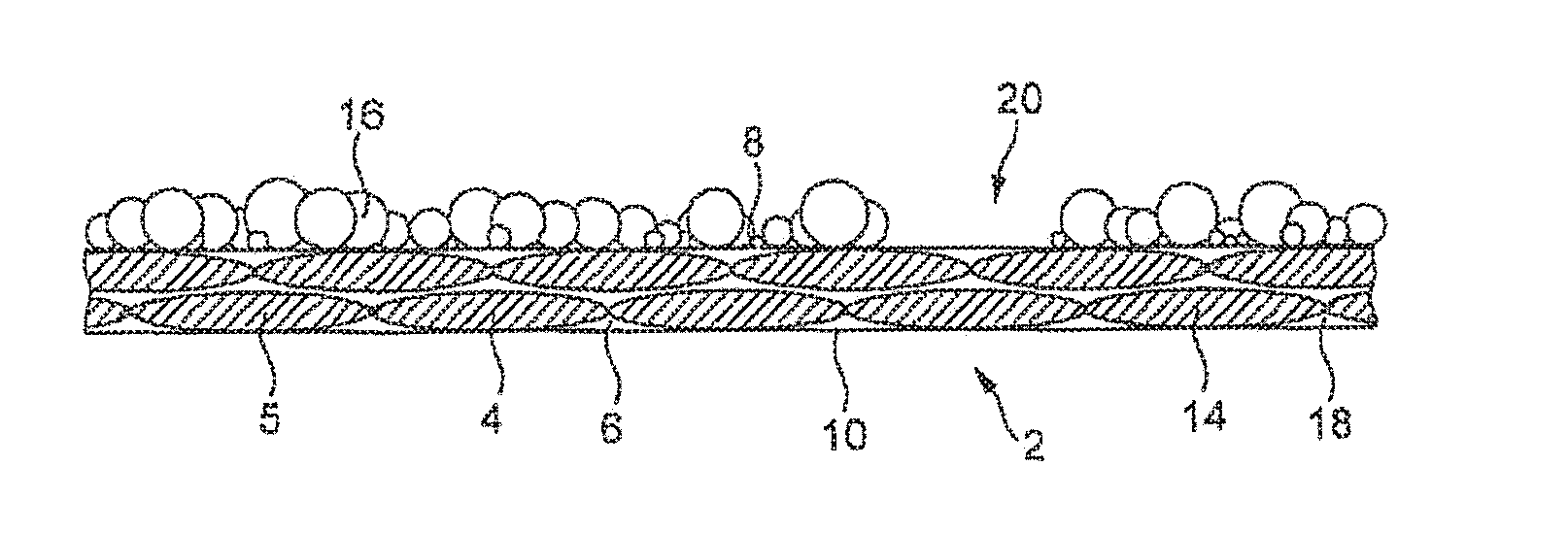
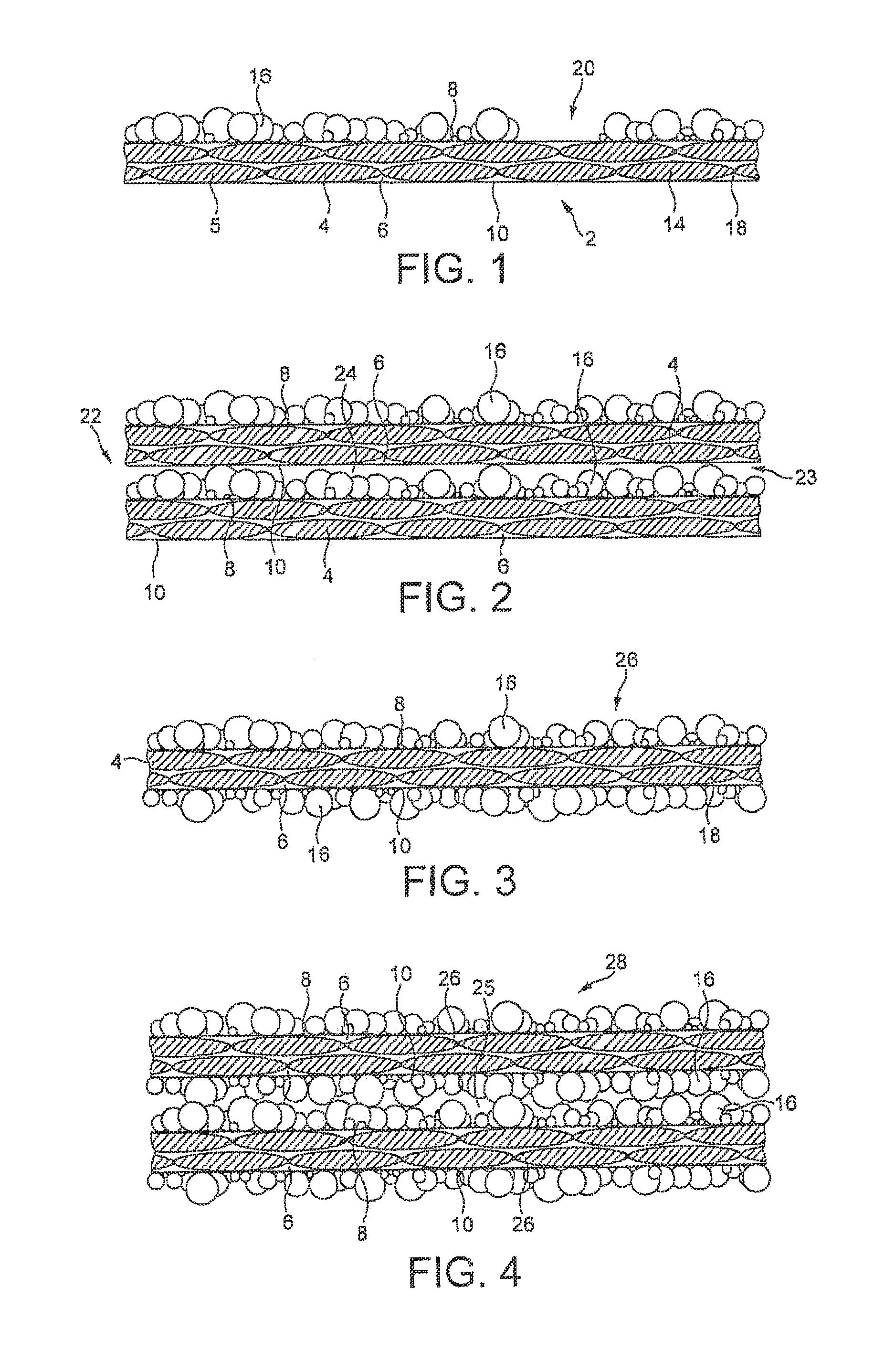
[0093]Referring to FIGS. 1 and 2, there is shown a prepreg 2 in accordance with a first embodiment of the present invention. For clarity of illustration, some dimensions in the drawings are exaggerated and only some of the fibres are shown.

[0094]The prepreg 2 comprises a layer of fibrous reinforcement 4, illustrated as a plurality of tows or fibre bundles 5, which is substantially fully impregnated by a matrix resin 6. The full impregnation provides that the opposed major surfaces 8, 10 of the prepreg 2 comprise resin surfaces. The resin 6 is typically an epoxy-functional resin including a latent curing agent, as is known in the art. Other resins, particularly thermosetting resins, may be employed. The fibrous reinforcement 4 comprises fibres 14 made of glass, carbon, aramid or similar materials. The fibres 14 are unidirectional (UD), being oriented in a common longitudinal direction perpendicular to the plane of the drawings of FIGS. 1 and 2. Preferably, the prepreg 2 is elongate a...


PUM

PropertyMeasurementUnit
particle sizeaaaaaaaaaa

Abstract

A prepreg for manufacturing a fibre-reinforced composite material, the prepreg including a body having a layer of fibrous reinforcement impregnated with a matrix resin material, and a powder coating layer of resin material on at least one major surface of the body and at least partly fused to the matrix resin material

Description

FIELD OF THE INVENTION[0001]The present invention relates to a prepreg for manufacturing a fibre-reinforced composite material and to a method of manufacturing such prepreg. The present invention further relates to the use of such a prepreg for manufacturing a fibre-reinforced composite material.BACKGROUND[0002]It has been known for many years in the field of fibre-reinforced composite materials to provide a prepreg which comprises a layer of fibrous reinforcement impregnated with a structural polymer resin. The amount of structural polymer resin is carefully matched with the amount of fibrous reinforcement. Accordingly, the prepreg may be used in a method for forming a fibre-reinforced composite material, in which a multilayer stack of prepregs is provided having a desired shape and configuration, and then is subjected to heating so that the structural polymer resin melts and then solidifies to form a single unified resin matrix in which the fibrous reinforcement is disposed in the...

Claims


Application Information

Patent Timeline
Patent Type & Authority Applications(United States)
IPC IPC(8): C08J5/24B32B5/26B32B37/10B05D1/06B05D3/02B05D3/12C08J7/04B05D1/12C08J7/05
CPCC08J5/24B32B2603/00B32B5/26B05D1/12B05D1/06B05D3/0263B05D3/12B32B37/1018C08J2363/00C08J2463/00B32B2255/02B32B2255/26B32B2260/046B32B2260/023C08J7/047B29C70/547B29C70/465B32B2262/101B32B2262/106B32B2307/52B32B2307/544C08J7/0427C08J7/05B32B27/38B32B37/003B05D2201/02B05D2252/10B05D2504/00B32B2305/076B32B2264/0214
Inventor SPENCER, PAULCADD, KEVIN STEVEN
Owner GURIT (UK) LTD
Why Eureka
Try Eureka