
Coatings for turbine parts

a turbine and coating technology, applied in the direction of superimposed coating process, liquid/solution decomposition chemical coating, machines/engines, etc., can solve the problems of material degradation, droplet erosion, increased dissipative losses, etc., and achieve the effect of simple and cost-effective solution

Active Publication Date: 2016-06-09
GENERAL ELECTRIC TECH GMBH
View PDF5 Cites 2 Cited by
  • Summary
  • Abstract
  • Description
  • Claims
  • Application Information

AI Technical Summary

Benefits of technology

The coating effectively reduces erosion and moisture-related losses, extending the lifespan of turbine blades and maintaining efficiency by providing a durable, hydrophobic barrier against condensate droplets and high temperatures.

Problems solved by technology

The relative wetness of the steam at the last stage of the low pressure stage may result in droplet erosion and other potential sources of performance losses as well as material degradation due to water droplet impact, requiring a need for additional spare parts to be exchanged.
However, the presence of a liquid phase in the rotating and stationary elements of the turbines may result in increased dissipative losses.
This moisture loss can result in a loss of efficiency of the low-pressure turbine of approximately 6-7%, which corresponds to a loss of efficiency of approximately 1-2% of an entire steam power plant.
This means that a part of the impulse of the working medium is not transferred onto the blades, which results in a moisture loss that reduces the degree of efficiency of the low-pressure turbine.
Furthermore, accumulation of water on the inside surfaces of the housing of the low-pressure turbine results in dissipative friction losses on the rotating vane tips and vane covers.
Finally, enlarged drops with diameters in the range from 100-200 microns and speeds in the range of more than 250 m / s cause erosion due to the impact of the drops.
This erosion depends greatly on the specific materials, whereby vane materials of titanium and titanium alloys, which are used preferably for the large blades of the low-pressure turbine, are especially susceptible.
Though a large number of such designs have been published, real-world applications of such composite blades are currently limited to gas turbines for advanced aircrafts engines.
One of the reasons which so far prevented large-scale adoption of composite blades in the field of electrical power generation is the lack of resistance of the composite materials to the erosion processes as described above.
Under the constant bombardment of the condensate from the water steam, composite material erodes much faster than the currently applied metal alloys and is thus are not suitable as airfoil material for large steam turbine blades.

Method used


Image

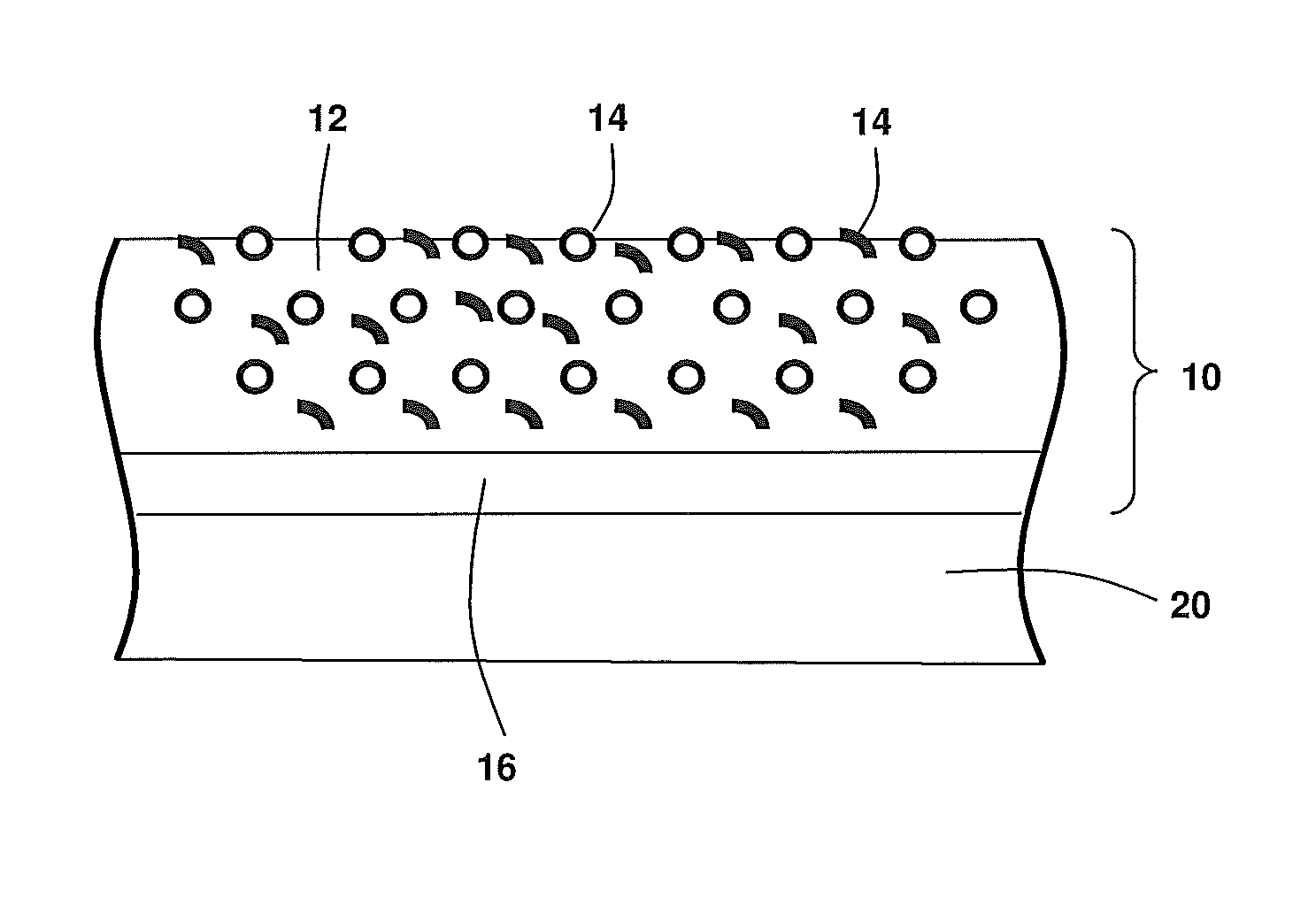
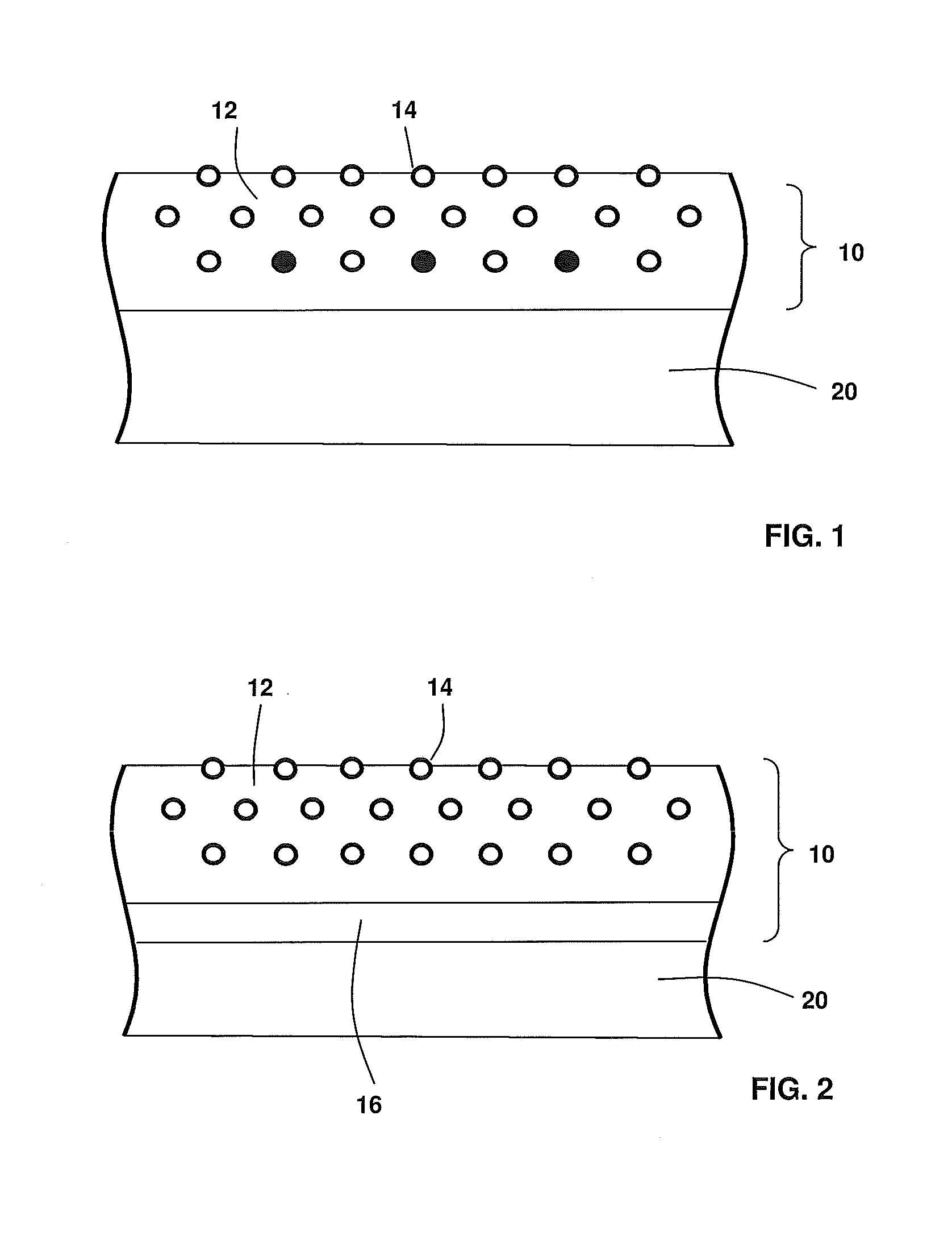
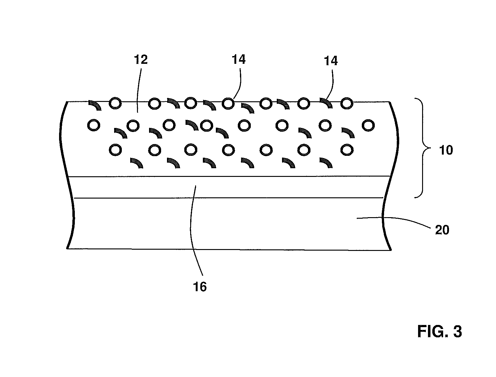
  • Coatings for turbine parts
  • Coatings for turbine parts
  • Coatings for turbine parts

Examples


Embodiment Construction

[0033]Throughout this specification the following terms have the following definitions

[0034]“Hydrophobic” is defined as a material with a contact angle, as measured by the static sessile drop method, between a solid surface of the material and a water droplet of greater than 90 degrees.

[0035]Siloxanes are defined as a functional group in organic silicon chemistry that has a Si—O—Si linkage. Siloxanes include polymeric hydrides, referred to as silicones or polysiloxanes that have the formulae H3—Si—[O—SiH2]n-O—SiH3 wherein hydrogen atoms may be substituted by halogens or organic groups.

[0036]The temperature resistance of specific polysiloxanes can be varied by varying the degree of cross linking and pyrolysis / hydrolysis in which there is a successive replacement of carbon containing end groups with oxygen to form SiO2. The result is an increase in the ceramic (SiO2) to organic ratio of the polysiloxane which increases the temperature resistance but typically has a detrimental effect ...


PUM

PropertyMeasurementUnit
temperaturesaaaaaaaaaa
volume %aaaaaaaaaa
volume %aaaaaaaaaa

Abstract

A method and a turbine part having a coating with a matrix layer that includes a high temperature resistant hydrophobic polysiloxane filler, wherein the coating has superior mechanical strength and temperature resistance.

Description

CROSS-REFERENCE TO RELATED APPLICATIONS[0001]This application claims priority to European application 13196979.2 filed Dec. 12, 2013, which in turn claims priority to European application 12198707.7 filed Dec. 20, 2012, both of which are hereby incorporated in their entireties.TECHNICAL FIELD[0002]The invention relates to the coating of turbine parts, particularly the blades of a low-pressure steam turbine, and to a long-lasting coating with hydrophobic properties for such parts.BACKGROUND[0003]In the following description the term “turbine” is used to refer to rotary engines having a stator and a rotating part force coupled by a fluid medium such as water or gas. Of particular interest for the present invention are axial turbines comprising radially arranged fixed stator blades or vanes alternating with radially arrangements of moving rotor blades. Movements are generally registered as movements relative to a casing or housing.[0004]In a large steam turbine, the pressurized steam i...

Claims


Application Information

Patent Timeline
Patent Type & Authority Applications(United States)
IPC IPC(8): C23C18/54C25D15/00C09D183/04
CPCC23C18/54C25D15/00C09D183/04C23C18/1662C23C18/36C23C28/027C23C30/00F05D2230/80F05D2230/31C25D3/12C25D5/50C23C18/1692Y10T428/31663F01D5/288Y02T50/60
Inventor WIDMER, THOMASOLLIGES, SVENSTANKOWSKI, ALEXANDERGRASSO, PIERO-DANIELEMELAS, MAUROBAUMANN, THOMAS
Owner GENERAL ELECTRIC TECH GMBH
Learn More