Magnetoresistive mixer

a magnetic field sensitivity and mixer technology, applied in the field of magnetic field sensitivity, can solve the problems of increasing increasing noise and greater power consumption, and increasing the complexity and power consumption of the circuit, so as to achieve high magnetic field sensitivity, low power consumption, and large output signal

Active Publication Date: 2016-06-09
MULTIDIMENSION TECH CO LTD
View PDF3 Cites 5 Cited by
  • Summary
  • Abstract
  • Description
  • Claims
  • Application Information

AI Technical Summary

Benefits of technology

[0009]In order to solve the above existing problems, the present invention describes a magnetoresistive mixer, wherein, by using the characteristic that the resistance of the magnetoresistive sensor is linearly proportional to changes of external magnetic fields, one frequency signal therein flowing through a spiral coil is converted to a magnetic field signal, another frequency signal is converted to a power signal to act upon the magnetoresistive sensor, the output signal of the magnetoresistive sensor is then a multiplication signal of two signals frequencies, the frequency content of the resulting signal is the sum or the difference thereof, there are no other redundant signals, and thus a filter and other elements are not required. Since the spiral coil and the magnetoresistive sensor are coupled by using a magnetic field, effective isolation between the input signals and between the input signals and the output signals is achieved. In addition, the magnetoresistive sensor further has the characteristics of low power consumption and high magnetic field sensitivity, and thus the current used to provide the magnetic field need not be too large in order to provide a large output signal, all of which ensure low power consumption and low noise.

Problems solved by technology

The active mixer uses a multiplier (e.g., a transistor or a vacuum tube) to increase strength of the product signal, by mixing an input signal at a frequency with a local frequency, producing an output signal with frequency components including the addition and subtraction of the two frequencies, and the active mixer increases the degree of isolation of two input ends, but it may have higher noise and greater power consumption.
1) The diode mixer uses an approximate processing method, such that the output signal, in addition to including a desired frequency, also has other frequencies, and these have signal strength that is relatively great; it is thus necessary to subsequently use a filter or other technologies to separate the interference in order to provide the desired signal.
2) The active mixer achieves frequency mixing by using a local oscillator, the output signal includes many other frequencies, it is also necessary to use a filter for separation, and it is necessary to use a multiplier, a local oscillator and other devices, which increases complexity and power consumption of the circuit.
3) The input signals and the output signals cannot be effectively isolated, and they will affect each other.

Method used


Image

  • Magnetoresistive mixer
  • Magnetoresistive mixer
  • Magnetoresistive mixer

Examples


embodiment 1

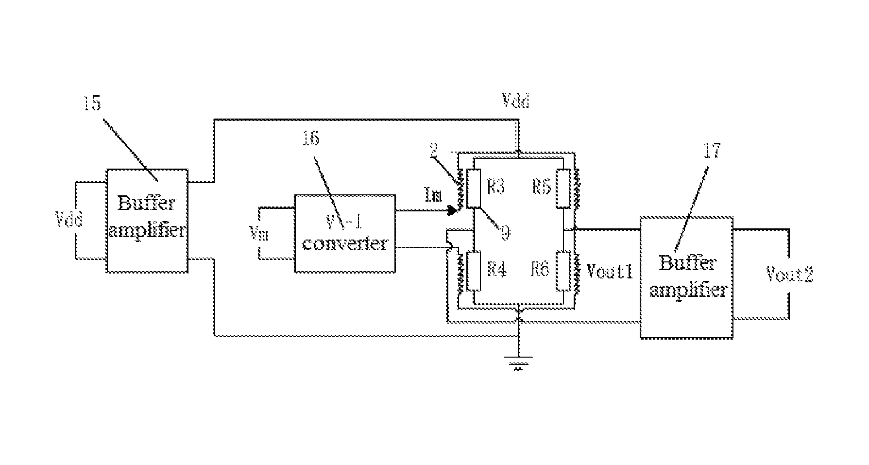
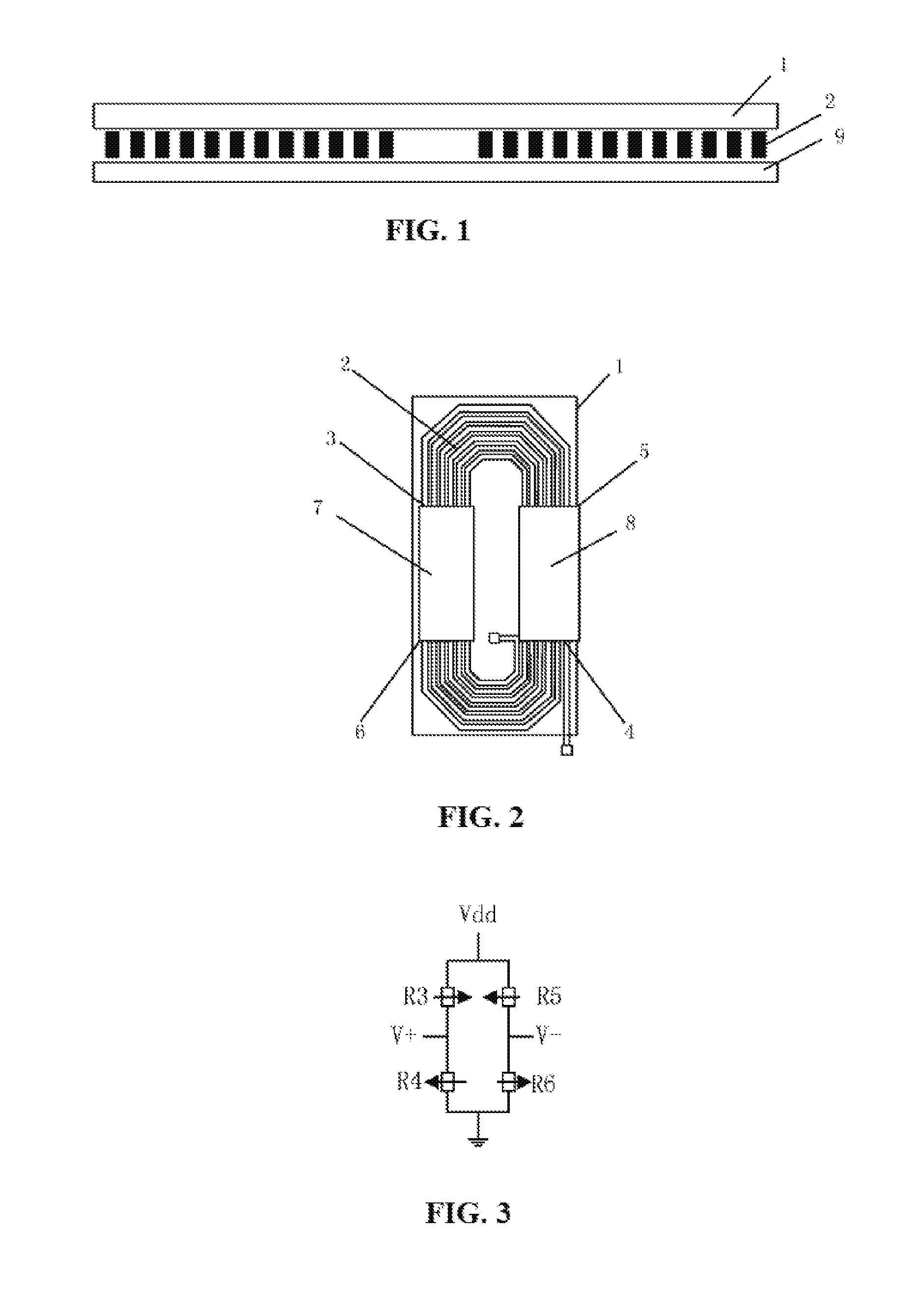
[0046]FIG. 1 is a sectional view of a magnetoresistive mixer, which includes a magnetic shielding layer 1, a spiral coil 2 and a bridge-type magnetoresistive sensor 9, wherein the spiral coil 2 is located between the magnetic shielding layer 1 and the bridge-type magnetoresistive sensor 9. In this embodiment, according to the direction shown in FIG. 1, the bridge-type magnetoresistive sensor 9 is located below the spiral coil 2. Certainly, it is also feasible to adopt a solution where the bridge-type magnetoresistive sensor 9 is located above the spiral coil 2.

[0047]The spiral coil is made of a high conductivity metal material (e.g., copper, gold, silver or the like), and it has a thickness of 1 μm to 20 μm and a width of 5 μm to 40 μm, where the spacing between two adjacent single coils is 10 μm to 100 μm.

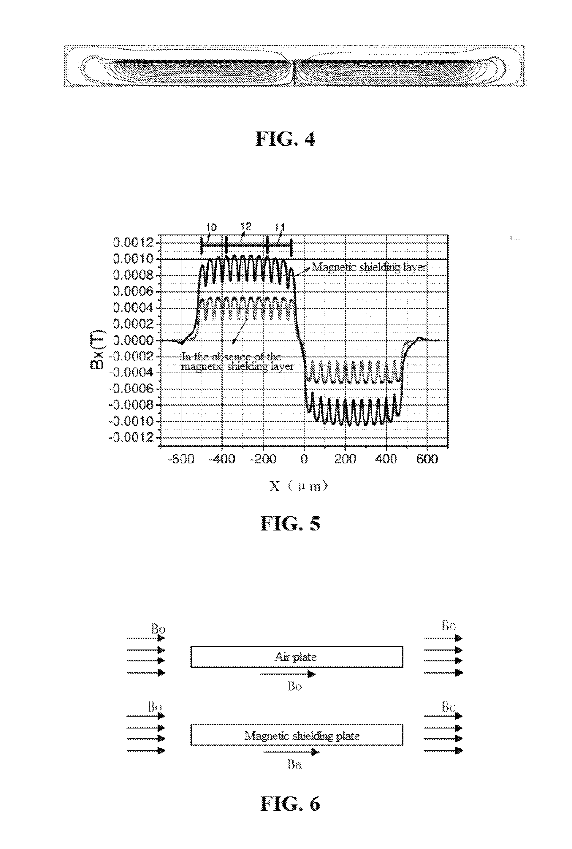
[0048]The magnetic shielding layer is made of a high permeability ferromagnetic alloy (e.g., NiFe, CoFeSiB, CoZrNb, CoFeB, FeSiB, FeSiBNbCu or the like), and has a thickness of 1 ...


PUM


Abstract

A magnetoresistive mixer, comprising a spiral coil, a bridge-type magnetoresistive sensor and a magnetic shielding layer, wherein the spiral coil is located between the bridge-type magnetoresistive sensor and the magnetic shielding layer. Four tunnel magnetoresistive sensor units forming the bridge-type magnetoresistive sensor respectively contain N array-type magnetic tunnel junction rows. The magnetic tunnel junction rows are connected in series, parallel, or combination of series and parallel connections to form two port structures. The four tunnel magnetoresistive sensor units are respectively located in two regions of the spiral coil having opposite current directions, sensing axes of magnetic tunnel junctions are perpendicular to the current directions, and in addition, the distribution characteristics of magnetic fields in directions of the sensing axes of the tunnel magnetoresistive sensor units to the magnetic field in the two regions are opposite, and the distribution characteristics in a single region are the same. The first frequency signal is input through the two ends of the spiral coil, the second frequency signal is input between the power and -ground ports of the bridge-type magnetoresistive sensor, and mixing signals are output through a signal output end of the bridge-type magnetoresistive sensor. The magnetoresistive mixer has the characteristics of good linearity, good input signal isolation, and low power consumption.

Description

TECHNICAL FIELD[0001]The present invention relates to the field of magnetic sensor technologies, and in particular, to a magnetoresistive mixer.BACKGROUND ART[0002]A mixer refers to an electronic device that converts an input signal with a frequency of f1 and an input signal with a frequency of f2 to an output signal having characteristic frequencies of f1+f2 and f1−f2. Through the mixer, the frequency of an input signal can be shifted to a higher frequency or a lower frequency value, so as to facilitate signal processing. For example, the frequency of a signal can be shifted by a mixer, in order to separate the signal from a noise signal, then noise can be filtered out using a filter, and the frequency of the signal is then shifted back to the original value using a mixer, in order to provide noise signal processing. Therefore, the mixers are widely used in signal processing circuit technologies.[0003]Mixers used currently include two types, i.e., a passive type and an active type....

Claims


Application Information

Patent Timeline
Patent Type & Authority Applications(United States)
IPC IPC(8): H03D7/00G01R33/00G01R33/09
CPCH03D7/00G01R33/0094G01R33/098H03D7/14H03D7/1491
Inventor ZHOU, ZHIMINDEAK, JAMES GEZA
Owner MULTIDIMENSION TECH CO LTD
Why Eureka
Try Eureka