Ultrasonic Rag Layer Detection System And Method For Its Use

a detection system and ultrasonic technology, applied in liquid/fluent solid measurement, instruments, volume measurement, etc., can solve the problems of increasing the cost of maintaining the separator vessel and downstream equipment, reducing the effect of dewatering process, and increasing the current demand

Inactive Publication Date: 2016-06-16
CAMERSON INT CORP
View PDF12 Cites 31 Cited by
  • Summary
  • Abstract
  • Description
  • Claims
  • Application Information

AI Technical Summary

Benefits of technology

[0039]Objectives of this invention include providing a system and method for detecting and measuring an interface emulsion or rag layer that (1) is non-ionizing; (2) is non-intrusive and, therefore, less likely to be affected by material building up; (3) uses ranging; (4) uses longitudinal waves; and (5) can be installed as a permanent fixture on a separator vessel.

Problems solved by technology

The layer, if left uncontrolled, can affect electrostatics, reduce the effect of dewatering processes, and increase the cost of maintaining the separator vessel and downstream equipment.
For example, the layer can grow in height until it interferes with the integrity of the electrostatic field, increasing the current demand and reducing the field strength.
If the layer sinks into the water layer, it rapidly occupies the water volume of the vessel, reduces the water residence time, and causes a decline in water quality being passed to downstream water treatment facilities.
Additionally, fluids within the vessel can experience changes in density due to variations in temperature, leading to measurement error.
These pressure sensor-based methods require the use of extremely low sensitivity sensors and, like the floats, are subject to material build-up problems leading to measurement error and maintenance issues.
These devices require a lot of power to drive the sensors, turbulence within the vessel can cause measurement errors, and the device is sensitive to material build up.
Material build up is also an issue with devices that make use of optical fiber sensors.
The sensors are not intrusive but water residing at the bottom of the vessel absorbs most of the energy, making detection of the emulsion layer difficult.
While highly accurate and able to withstand harsh environments, cost and safety are issues.
To detect the fluid level without use of intrusive probes, the systems require various zigzag interrogation path locations and orientations and this complicated arrangement is unsuitable for easily determining the location of two or more fluids in the vessel.
This technique, which does not make use of ranging, is only feasible at the interface between boundaries—e.g., pipe wall / transducer / fluid interface—and not any distance from that boundary.
Radioactive based technologies are difficult to convince operators to adopt because of safety concerns.

Method used


Image

  • Ultrasonic Rag Layer Detection System And Method For Its Use
  • Ultrasonic Rag Layer Detection System And Method For Its Use
  • Ultrasonic Rag Layer Detection System And Method For Its Use

Examples


Embodiment Construction

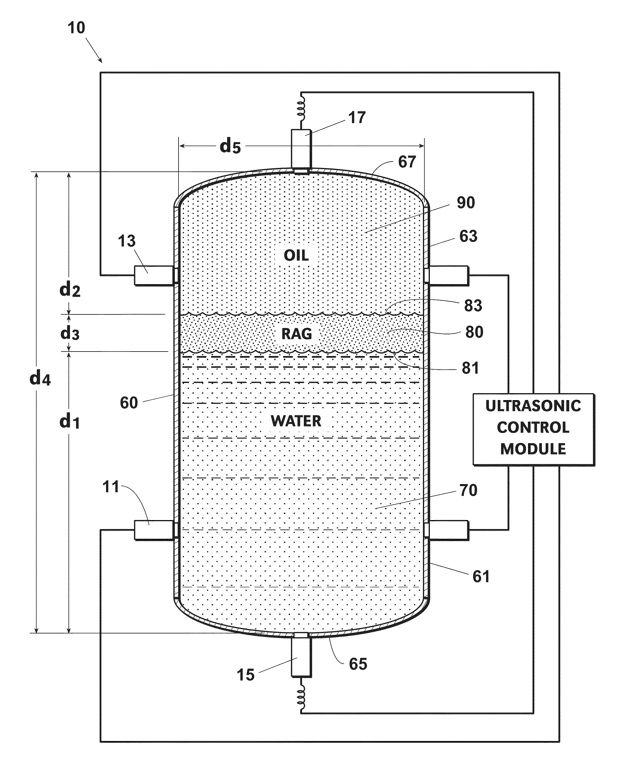
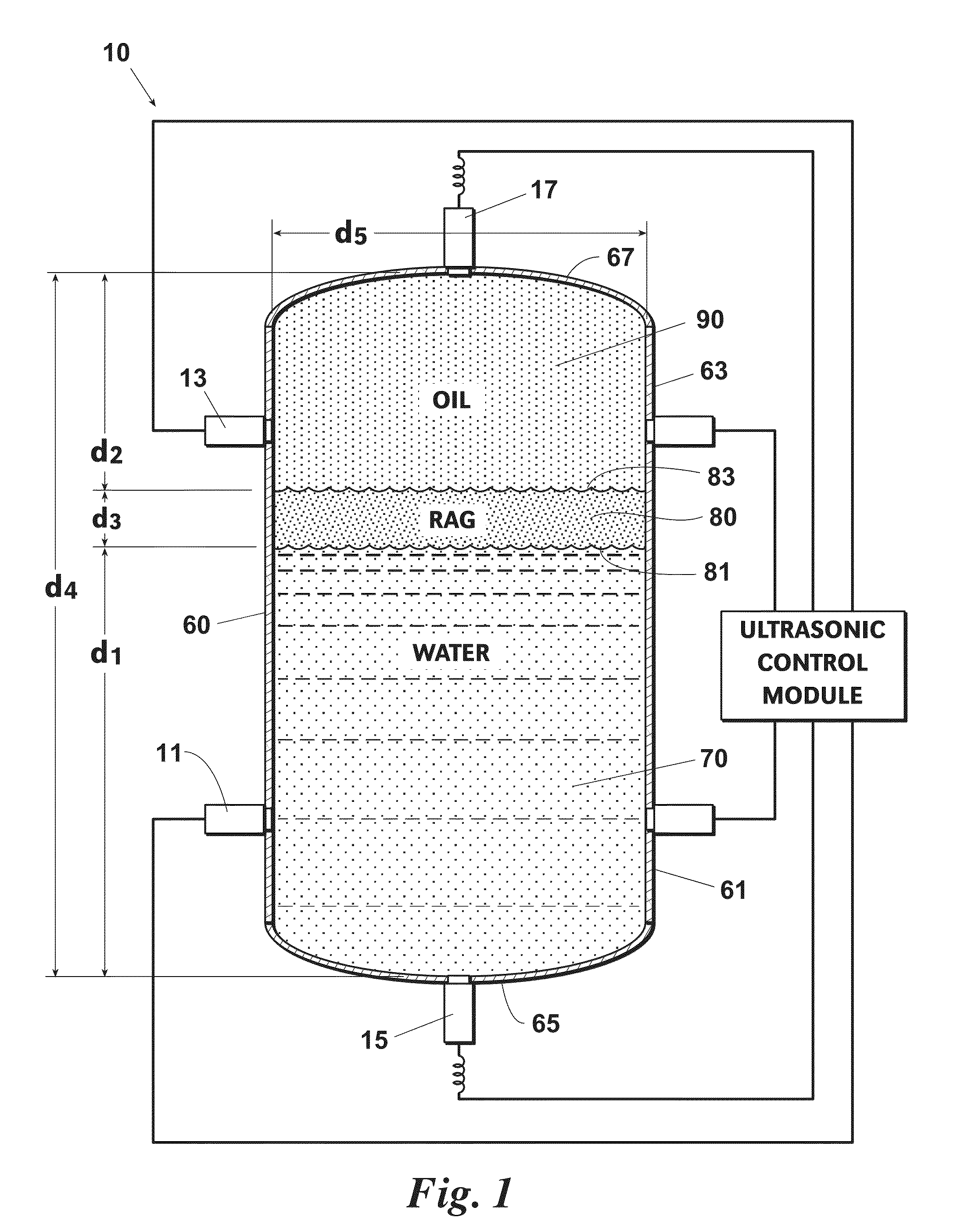
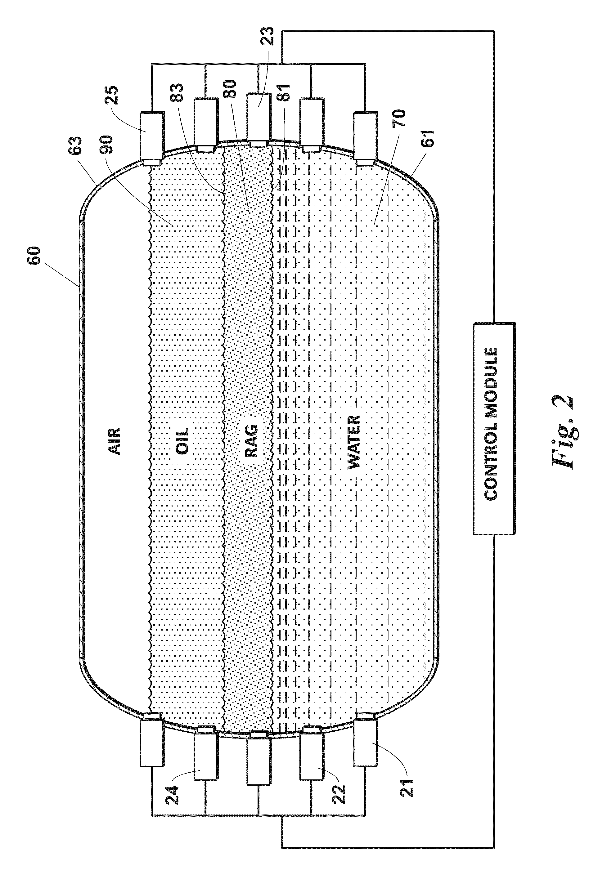
[0075]A system and method for detecting and locating the interface emulsion or rag layer in a separator vessel makes use of an acoustic property approach or an imaging approach. Both approaches make use of ranging (pulse echo) and longitudinal (not shear) mode reflectance and are non-ionizing. The signals are sent through the fluid medium and not through the vessel wall or a probe surrounded by the fluid medium.

[0076]The acoustic property approach relies upon differences in acoustic impedance between the oil, rag, and water layers that create an echo detected by transit time measurement. Also, the velocity of sound, density, viscosity and attenuation can be calculated for each fluid in order to determine whether the medium is oil, rag, or water. The imaging approach employs differences in amplitude reflectance at these interfaces to create a brightness mode image of the different layers by each amplitude mode scan line being added spatially.

[0077]A separator vessel is equipped with ...


PUM

PropertyMeasurementUnit
ultrasonic frequencyaaaaaaaaaa
frequencyaaaaaaaaaa
frequency fLaaaaaaaaaa

Abstract

A system and method for detecting and locating the interface emulsion or rag layer in a separator vessel makes use of an acoustic property approach or an imaging approach. Both approaches use ranging and longitudinal mode reflectance and are non-ionizing. The signals are sent through the fluid medium residing in different zones of the vessel, not through the vessel wall or a probe surrounded by the fluid medium. The acoustic property approach uses differences in acoustic impedance between the oil, rag, and water layers that create an echo detected by transit time measurement. Also, the velocity of sound, density, viscosity and attenuation can be calculated for each fluid in order to determine whether the medium is oil, rag, or water. The imaging approach uses differences in amplitude reflectance at these interfaces to create a brightness mode image of the different layers by each amplitude mode scan line being added spatially.

Description

BACKGROUND OF THE INVENTION[0001]This invention relates to systems and methods used to detect an interface emulsion or rag layer within a separator vessel. More specifically, the invention relates to non-radioactive-based, ultrasonic technologies using longitudinal waves to detect the interface emulsion or rag layer and determine its location and depth.[0002]The basic method of separating a mixture of oil and water is by use of gravity. For this purpose, separators are frequently employed at the point where the crude oil first reaches the earth's surface. These separators range from rather unsophisticated holding vessels—which simply provide an enclosed container wherein the oil-and-water mixture can rest with reduced turbulence, thereby allowing the oil to float to an upper part of the vessel and water to settle to a lower part of the vessel—to more sophisticated vessels that apply desalting and dehydration methods. The goal is to produce a stabilized crude oil with basic sediment ...

Claims


Application Information

Patent Timeline
Patent Type & Authority Applications(United States)
IPC IPC(8): G01N29/02G01N29/26G01N29/36
CPCG01N29/02G01N29/36G01N2291/0224G01N2291/106G01N29/26G01F22/00G01F23/2962G01N29/024G01N29/032G01N29/222G01N29/262G01N29/4418G01N2291/02818G01N2291/044G01N2291/0222G01F23/296
Inventor GOTTLIEB, EMANUELAUGENSTEIN, DONALDSAMS, GARY W.
Owner CAMERSON INT CORP
Why Eureka
Try Eureka