Bidirectional dc-dc converter

a dc-dc converter and bi-directional technology, applied in the direction of electric variable regulation, process and machine control, instruments, etc., can solve the problems of reducing the efficiency of dc-dc converters. , to achieve the effect of enhancing voltage conversion performance, reducing power loss, and tolerating large fluctuations of input voltag

Inactive Publication Date: 2016-06-23
NAT CHUNG SHAN INST SCI & TECH
View PDF4 Cites 35 Cited by
  • Summary
  • Abstract
  • Description
  • Claims
  • Application Information

AI Technical Summary

Benefits of technology

[0006]In view of the aforesaid drawbacks of the prior art, it is an objective of the present invention to provide a bidirectional DC-DC converter which applies to a battery-equipped charging and discharging system and is connected between two DC power sources to perform bidirectional discharging and charging, stabilize an output voltage, and tolerate large fluctuations of an input voltage, so as to enhance voltage conversion performance and reduce power loss.

Problems solved by technology

The instability in voltage is likely to cause damage to electrical appliances.
A conventional buck-boost converter has an inverter whose output end is provided with a low-frequency transformer for effectuating insulation and voltage level conversion; as a result, the conventional buck-boost converter is disadvantageously rendered bulky, heavy, and inefficient.
Another conventional high-frequency transformer, which is compact and lightweight, has a bidirectional DC-DC converter framework and is characterized in that: although it is easy to control, its input voltage varies with the battery voltage; the number of turns of the winding of a conventional transformer is designed according to the minimum battery voltage; hence, when the battery voltage reaches its maximum, the input voltage is likely to be overly high, and thus it necessitates components which tolerate high voltages, thereby adding to the system costs and increasing conduction loss; in addition to the bidirectional DC-DC converter framework, it comes with a current source push-pull circuit structure whose input end has an inductor capable of generating a current source, and thus it requires a switch buffer circuit for decreasing a voltage surge produced at the instant of switch cut-off; to augment high-efficiency recycle leakage inductance energy and allow the switch to undergo zero voltage switching (ZVS), the prior art discloses an additional clamp circuit, but it brings about a drawback, that is, in a high-voltage application scenario, the switch voltage is overly high.
As a result, although a conventional DC-DC converter series-connected buck-boost converter solves known problems with large variations in a battery voltage and high-voltage application, it still has drawbacks, for example, the need for augmenting a primary circuit in a series-connected manner at the expense of operation efficiency and manufacturing costs.
As indicate by the above prior art, the input voltage of conventional bidirectional DC-DC converters is restricted in the state of battery voltage charging and discharging and thus manifests large fluctuations.
As a result, they require components which tolerate high voltages, thereby adding to the system costs and incurring high conduction loss.
In this regard, even though switch cut-off surge is reduced by a switch buffer circuit, the problem with overly high switch voltage remains unsolved.
If buck-boost converters are connected in series, the operation efficiency will decrease, thereby adding to the manufacturing costs.
Although the circuit framework of Taiwan invention patent 1397250 cuts costs and reduces conduction loss, it is still inapplicable to a battery-equipped charging and discharging system.

Method used


Image

  • Bidirectional dc-dc converter
  • Bidirectional dc-dc converter
  • Bidirectional dc-dc converter

Examples


first embodiment

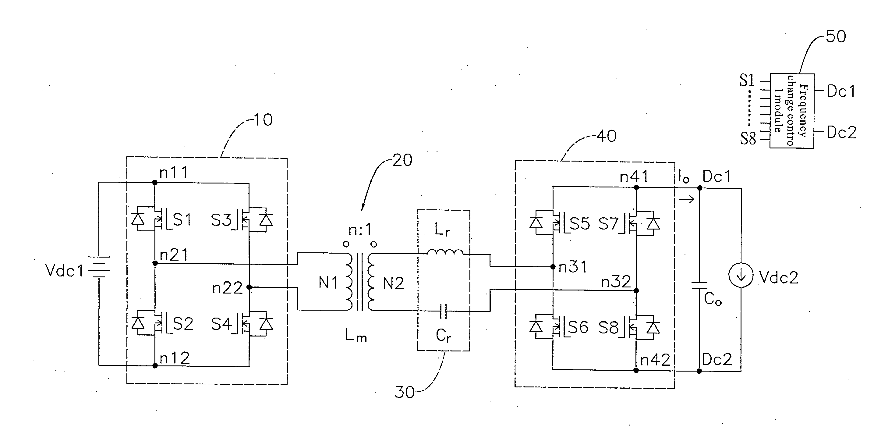
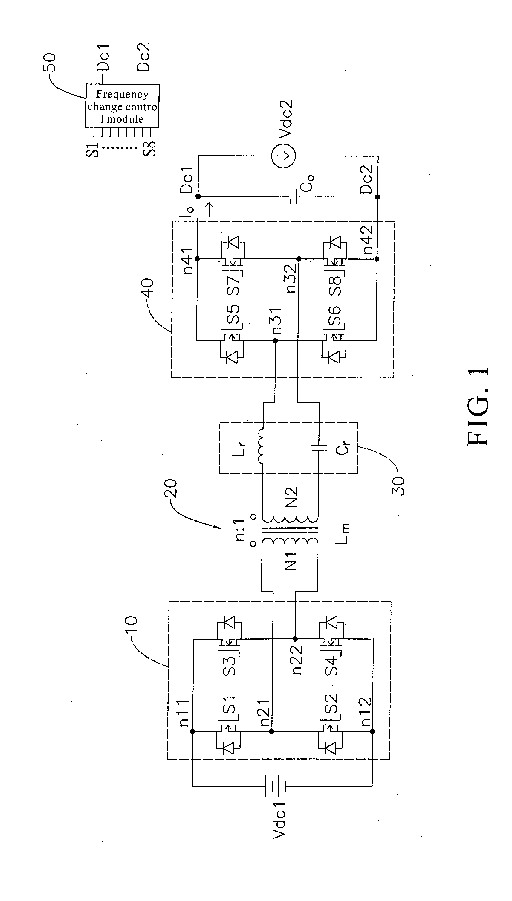
[0021]Referring to FIG. 1, there is shown a circuit diagram of a bidirectional DC-DC converter according to the present invention. The bidirectional DC-DC converter applies to a battery-equipped charging and discharging system and especially to stabilizing an output voltage despite large fluctuations of an input voltage. The bidirectional DC-DC converter comprises a first DC power source Vdc1, a second DC power source Vdc2, a first full-bridge switching unit 10, a transformer 20, a resonance unit 30, a second full-bridge switching unit 40, and a frequency change control module 50. In this embodiment, the first DC power source Vdc1 is a chargeable and dischargeable battery, and the second DC power source Vdc2 is connected to an inverter (not shown).

[0022]The first full-bridge switching unit 10 comprises first through fourth switches S1˜S4 and forms two input-oriented first nodes n11, n12 and two output-oriented second nodes n21, n22. The first nodes n11, n12 are connected to the firs...

second embodiment

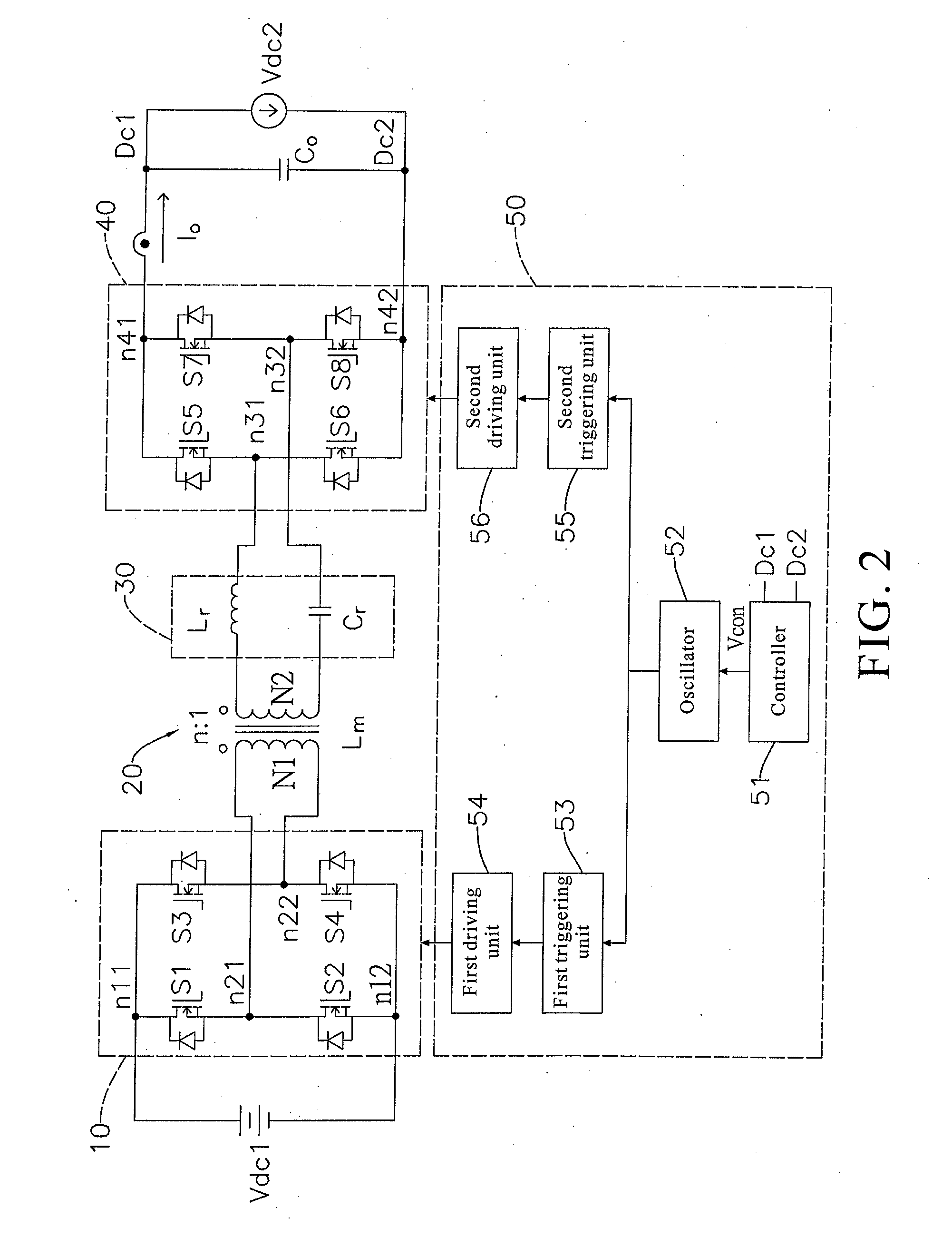
[0027]The frequency change control module 50 is connected to the first through fourth switches S1˜S4 of the first full-bridge switching unit 10 and the fifth through eighth switches S5˜S8 of the second full-bridge switching unit 40. The frequency change control module 50 detects the state of the second DC power source Vdc2 and instructs the first full-bridge switching unit 10 and the second full-bridge switching unit 40 to operate in accordance with the state of the second DC power source Vdc2. Furthermore, the frequency change control module 50 reduce the power loss of the switches S1˜S8 by zero voltage switching. Moreover, the frequency change control module 50 not only changes the operating frequency and receives a control signal so as to adjust the voltage gain ratio and thus adapts to large fluctuations of the input voltage, but also controls the first full-bridge switching unit 10 and the second full-bridge switching unit 40 to perform boost discharging or buck charging so as ...


PUM


Abstract

A bidirectional DC-DC converter applies to a charging and discharging system equipped with a battery and especially to power fluctuations arising from the charging and discharging of the battery. The bidirectional DC-DC converter has a first full-bridge switching unit, transformer, resonance unit, second full-bridge switching unit, and frequency change control module. The first full-bridge switching unit connects with a first DC power source. The transformer has a primary side connected to the first switching unit to receive a power from the first DC power source and has a secondary side connected to the second full-bridge switching unit. The resonance unit connects with the transformer's secondary-side winding and receives power to produce resonance. The second full-bridge switching unit connects with a second DC power source. The frequency change control module instructs the switching units to perform bidirectional buck-boost switching and changes the operating frequency to adjust voltage gain.

Description

FIELD OF TECHNOLOGY[0001]The present invention relates to DC-DC converters, and more particularly, to a bidirectional DC-DC converter for use in a charging and discharging system.BACKGROUND[0002]A unidirectional DC-DC converter is not only an indispensable power converter of a conventional power conversion system but is also a power converter in widest use. The unidirectional DC-DC converter comprises a buck converter, a boost convert, and a buck-boost converter which are grounded at one end in a non-insulated manner, and is often disposed between a utility electricity source and a load device. The bidirectional DC-DC converter also widely applies to a battery-equipped charging and discharging system, such as an uninterruptible power system, a battery power-storing system, a grid-style power-storing system, an inverter, a charger, an uninterruptible power supply (UPS), an on-board charger, a mixed power generating system, and a microgrid system. The input voltage is restrained by th...

Claims


Application Information

Patent Timeline
Patent Type & Authority Applications(United States)
IPC IPC(8): H02M3/335
CPCH02M3/33507H02M3/33584H02M1/0058Y02B70/10
Inventor CHIANG, HSUANG-CHANGJEN, KUO-KUANGYOU, GWO-HUEILIU, KE-CHIH
Owner NAT CHUNG SHAN INST SCI & TECH
Why Eureka
Try Eureka