Phase error detector and optical disc device

a detector and optical disc technology, applied in the field of phase error detectors and optical disc devices, can solve problems such as the decrease of recording capacity, and achieve the effect of reducing the residual of a pll

Active Publication Date: 2016-06-30
PANASONIC INTELLECTUAL PROPERTY MANAGEMENT CO LTD
View PDF1 Cites 1 Cited by
  • Summary
  • Abstract
  • Description
  • Claims
  • Application Information

AI Technical Summary

Benefits of technology

[0012]The present disclosure provides a phase error detector and an optical disc device that reduces a residual of a PLL without adding an analog circuit having a large circuit area.
[0014]According to the phase error detector and the optical disc device in the present disclosure, increasing a gain of the phase error detector can reduce a residual of a PLL using the same.

Problems solved by technology

However, since user data cannot be recorded on a portion where the pre-pits are formed, a recording capacity decreases.

Method used


Image

  • Phase error detector and optical disc device
  • Phase error detector and optical disc device
  • Phase error detector and optical disc device

Examples


exemplary embodiment 1

1-1. Configuration of Optical Disc

[0025]First, an optical disc on which an optical disc device of the present exemplary embodiment performs recording or reproduction will be described.

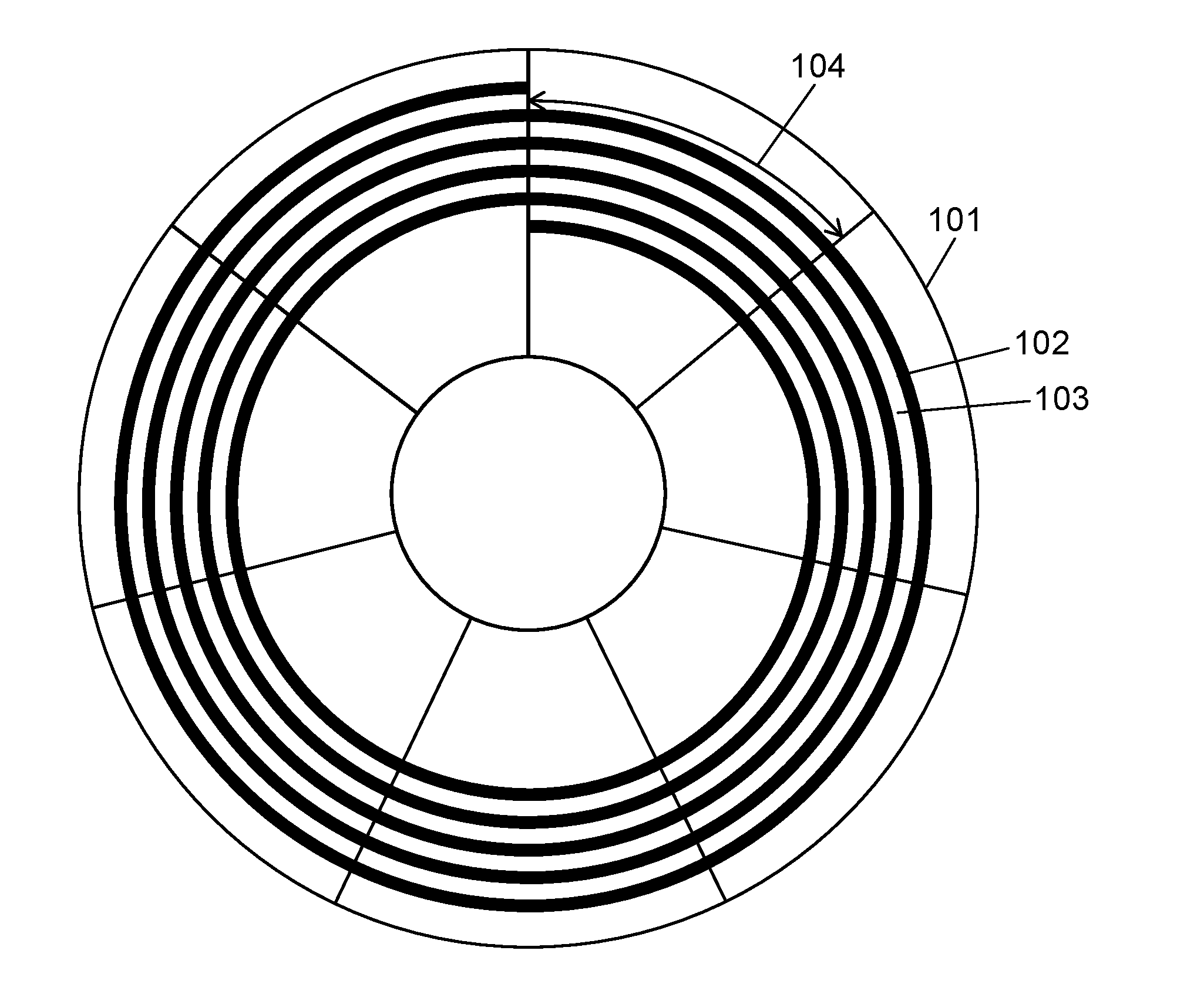
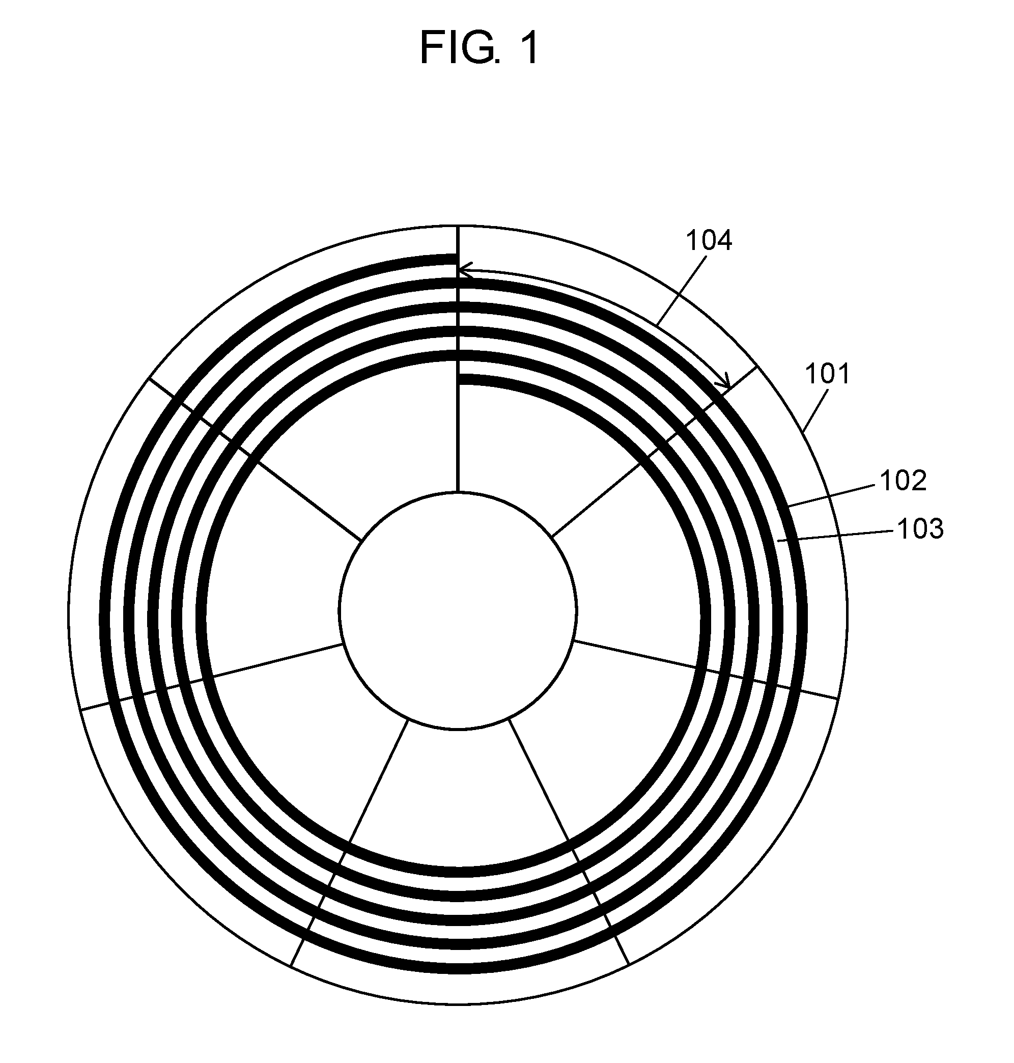
[0026]FIG. 1 is a schematic diagram of the optical disc on which the recording or reproduction is performed in the optical disc device of the present exemplary embodiment. As shown in FIG. 1, optical disc 101 has groove track (hereinafter, groove) 102 which is formed in a spiral shape. Land track (hereinafter, land) 103 is formed in a portion sandwiched between groove 102 and groove 102. In optical disc 101, groove 102 and land 103 are used as recording tracks.

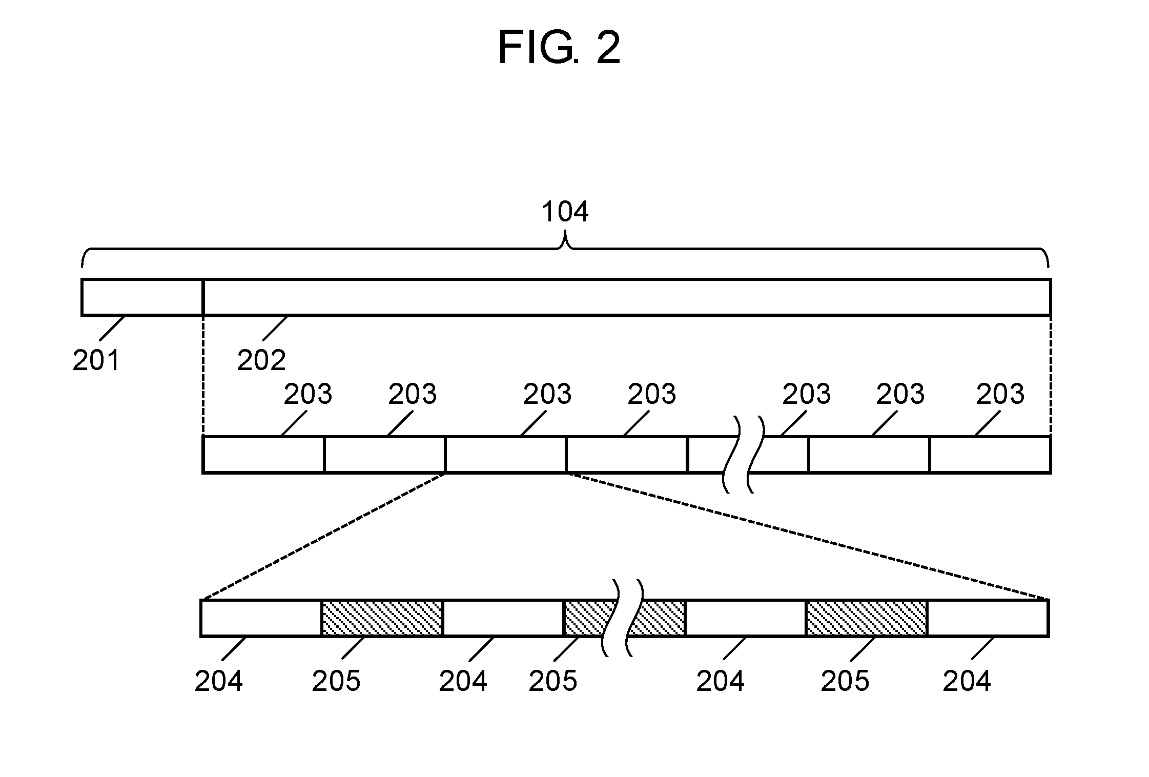
[0027]Groove 102 and land 103 form ADdress In Pre-Groove (ADIP) 104 by radially dividing the track into seven equal parts. ADIP 104 has address information indicating a position in optical disc 101. ADIP 104 is an address information unit in optical disc 101. Since ADIP 104 is formed by radially divided the track, a length of ADIP 104 differs, de...


PUM

PropertyMeasurementUnit
frequencyaaaaaaaaaa
phaseaaaaaaaaaa
phase differenceaaaaaaaaaa

Abstract

A phase error detector includes a sine wave generation circuit that generates a sine wave signal, based on a first input signal of a first period, a cosine wave generation circuit that generates a cosine wave signal, based on the first input signal, a first calculator that calculates a phase difference between the sine wave signal and a second input signal of a second period, a second calculator that calculates a phase difference between the cosine wave signal and the second input signal, and a first selection unit that outputs the phase difference calculated by the first calculator when the phase difference calculated by the second calculator is within a predetermined range, and outputs a predetermined value having a same sign as a sign of the phase difference calculated by the first calculator when the phase difference calculated by the second calculator is out of the predetermined range.

Description

BACKGROUND OF THE INVENTION[0001]1. Field of the Invention[0002]The present disclosure relates to a phase error detector used in Phase Locked Loop (PLL) circuit, and an optical disc device that detects address and records, using a generated clock.[0003]2. Description of the Related Art[0004]In recent years, recording density of an optical disc goes on increasing. In a field of video technology, optical discs such as a Digital Versatile Disc (DVD) and a Blu-ray (registered trademark) Disc (BD) and the like are well known. These optical discs are used as media for recording video data and also used as external storage media of personal computers. Meanwhile, as external storage media for personal computers, hard disks, flash memories and the like are also used. Compared with such media, the optical disc media have advantages of long life, high reliability, and no power necessity for retaining data.[0005]In view of the advantages, optical disc media attract attention as archive media fo...

Claims


Application Information

Patent Timeline
Patent Type & Authority Applications(United States)
IPC IPC(8): G11B20/10
CPCG11B20/1024G11B7/0053G11B7/0941G11B7/24082G11B20/10222G11B2007/00754G11B2020/1268
Inventor MINAMINO, JUNICHINAKATA, KOHEI
Owner PANASONIC INTELLECTUAL PROPERTY MANAGEMENT CO LTD
Why Eureka
Try Eureka