
Antenna structure based on millimeter wave and operation method thereof

a technology of millimeter wave and antenna structure, applied in the direction of resonant antennas, individually energised antenna arrays, wireless commuication services, etc., can solve the problems of large signal attenuation, short reaching distance, strong linearity, etc., and achieve the effect of reducing the possibility of connection severan

Inactive Publication Date: 2016-06-30
ELECTRONICS & TELECOMM RES INST
View PDF8 Cites 71 Cited by
  • Summary
  • Abstract
  • Description
  • Claims
  • Application Information

AI Technical Summary

Benefits of technology

The invention provides information on designing antenna structures for base stations and terminals in a mobile communication system using millimeter waves. It discusses the use of millimeter waves as a way to reduce interference and connectivity issues in the network. The invention also suggests using a multi-layer dynamic cell with beamforming antennas to improve coverage and efficiency. Overall, the invention aims to simplify the design process and improve the performance of millimeter wave wireless networks.

Problems solved by technology

However, design and implementation of a cellular system using the millimeter wave may be very challenging in five viewpoints described below.
First, in a viewpoint of “reaching distance and linear communication”, communication is performed only in LOS because path loss increases in proportion to the square of the frequency at a higher frequency, and as a result, the reaching distance is short and linearity is strong.
Second, in a viewpoint of “shadowing”, since the millimeter wave is sensitive to shadowing, when the millimeter wave meets an obstacle (e.g., bricks) once, very large signal attenuation can occur and fading may occur due to humidity and rain.
Third, in a viewpoint of “rapid channel variation and frequent connection severance”, when a terminal moves, a channel coherence time decreases with the higher frequency (for example, when the terminal moves, Doppler spread relatively increases and a channel varies per usec as compared with the cellular frequency) and when the obstacle is generated, the path loss may show rapid swing.
Consequently, such a phenomenon has a problem in that connection is increasingly abruptly stopped and rapid adaptation to a situation in which a communication environment suddenly stops is required from the viewpoint of the system.
Among the aforementioned viewpoints, in terms of “reaching distance and linear communication” and “shadowing”, the path loss increases with the higher frequency, but when an antenna gain is increased through a beamforming technology and the linear communication is induced through beam steering using an RF antenna assembly technology, it is possible to comes close to free space loss of a frequency actually used in the existing cellular system.

Method used


Image

  • Antenna structure based on millimeter wave and operation method thereof
  • Antenna structure based on millimeter wave and operation method thereof
  • Antenna structure based on millimeter wave and operation method thereof

Examples


exemplary embodiment 1

BPH-Based Stacked Base Station Antenna Structure Having Frequency Division Overlapping Beam Layout Structure

[0104]FIG. 7 is a diagram illustrating one example of beam planning using effective divided projection beam areas according to an exemplary embodiment of the present invention.

[0105]The example of the layout illustrated at the lower end of FIG. 6 may perform beam planning illustrated in FIG. 7 (while beams that belong to Part 1 are prevented from overlapping with each other and beams that belong to Part 2 are also prevented from overlapping with each other, a coverage hole part of Part 1 is covered by Part 2 and on the contrary, a coverage hole part of Part 2 is covered by Part 1). In this case, the antenna structure of the base station is similar to that of FIG. 4. Unlike the non-overlapping beam layout structure at the upper end of FIG. 6, the location of the beamforming antenna mounted on the BPH may vary. The layout has an advantage in that rapid performance deterioration ...

exemplary embodiment 2

Group Beamforming Antenna Based Stacked Base Station Antenna Structure

[0106]FIG. 8 is a diagram illustrating an example considering mechanical tilting of a beamforming antenna according to an exemplary embodiment of the present invention.

[0107]In the entire base station antenna structure of FIG. 4 to which the overlapping beam layout structure of FIG. 7 is applied, the location of the beamforming antenna for each BPH is maintained as it is and the mechanical tilting may be considered by separating the beamforming antenna into beamforming antennas of PART 1(FA1,2,3,4) and PART 2(FA5,6,8,9) as illustrated in FIG. 8. In this case, the entire base station antenna structure of FIG. 4 may not be changed any longer. However, when the beamforming mounting antennas in the BPH are disposed at a regular interval, a tilting angle may be increased.

[0108]As various examples, in a mmWave-based multi-sector beam cellular system, as a second type of the base station antenna structure, the beamformin...

exemplary embodiment 3

Method for Configuring Multi-Layer Dynamic Cell in mmWave-Based Multi-Spot Beam Cellular Environment

[0145]FIG. 20 is a diagram illustrating multiple spot beams using multiple beamforming antennas.

[0146]Referring to FIG. 20, the multiple spot beams may be provided in a form in which a beam is radiated from the center and formed on the bottom surface by using multiple beamforming antennas (e.g., 57) in a base station. One spot beam coverage may be actually constituted by 8 spot beam component carriers (57*8). In the multiple spot beams configured as above, one or more BCCs corresponding to the same layer (the same FA) are gathered to make the cell. That is, one BCC may be one cell, but multiple BCCs may make one cell.

[0147]FIG. 21 is a diagram illustrating a beam component carrier for each of the multiple layers.

[0148]Referring to FIG. 21 when 8 FAs are regarded as a multi-layer concept, 57 beam component carriers may be present for each of the 8 layers (alternatively, for each layer)...


PUM


Abstract

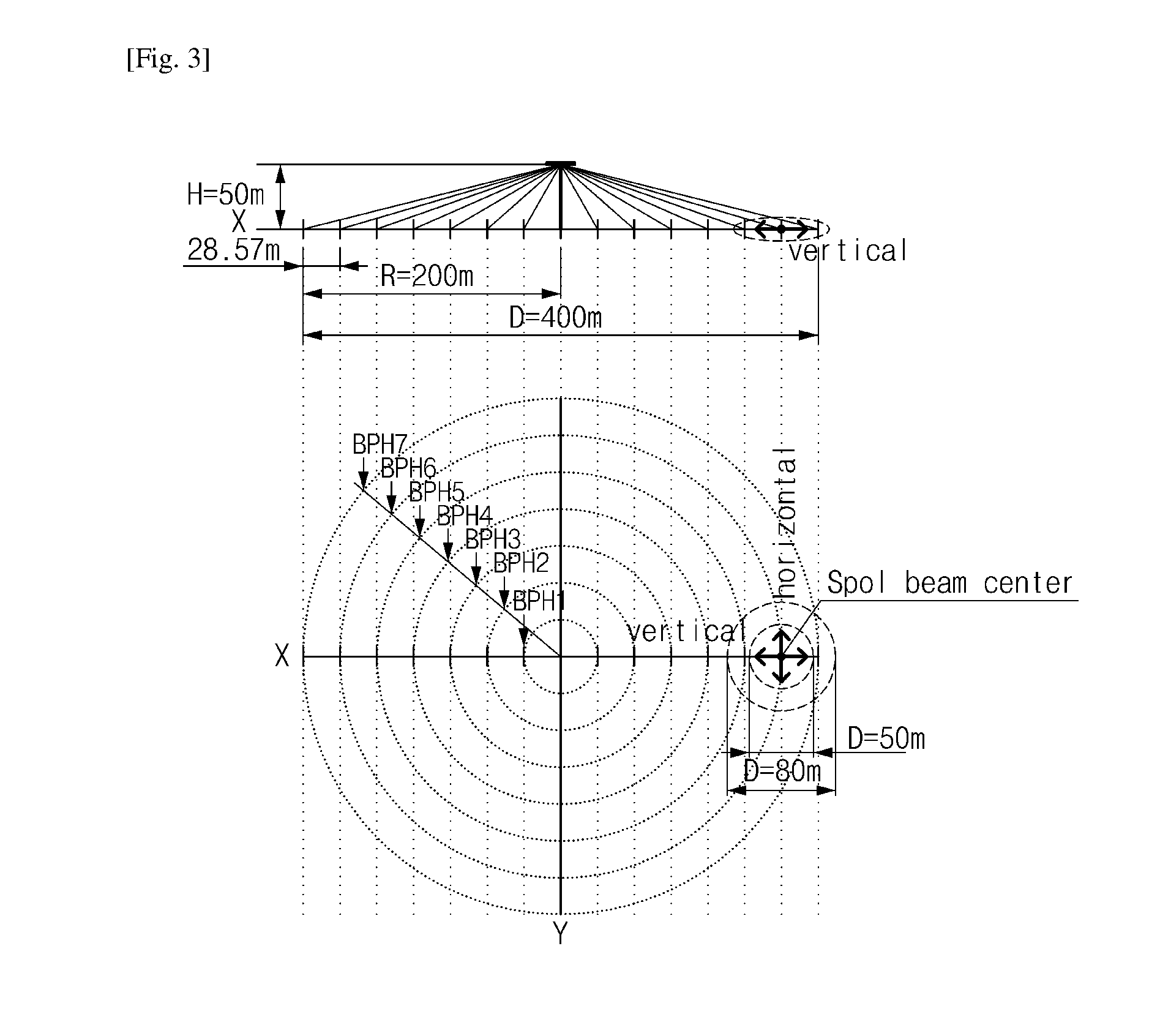
Provided is an antenna structure of a base station, comprising: at least one beamforming disposed to include an effective beam area having a first diameter and a non-overlapping beam area having a second diameter as a projection criterion of a bottom surface at a spot beam center of a spot beamby considering characteristics, performance, a base station coverage, and a height of the beamforming antenna and disposed so that the second diameter is smaller than the first diameter by a designated size. Accordingly, an enhanced communication based on a millimeter wave is provided.

Description

CROSS-REFERENCE TO RELATED APPLICATIONS[0001]This application claims priority to and the benefit of Korean Patent Application No. 10-2014-0192614 filed in the Korean Intellectual Property Office on Dec. 29, 2014, No. 10-2014-0192615 filed in the Korean Intellectual Property Office on Dec. 29, 2014, No. 10-2015-0047193 filed in the Korean Intellectual Property Office on Apr. 3, 2015 and No. 10-2015-0047194 filed in the Korean Intellectual Property Office on Apr. 3, 2015 the entire contents of which are incorporated herein by reference.TECHNICAL FIELD[0002]The present invention relates to a technology associated with design and operation of a cell mobile communication system using a millimeter wave.BACKGROUND ART[0003]In a mobile communication system, as a method for preparing for heavy increase in mobile traffic, three methods are generally currently proposed. A first method is to increase spectrum efficiency of a frequency, a second method is to further increase a use frequency, and...

Claims


Application Information

Patent Timeline
IPC IPC(8): H01Q21/06H01Q3/24H04W36/30H04B7/06H04W36/00H04W36/08H01Q9/04H01Q25/00
CPCH01Q21/065H01Q9/0407H01Q3/24H04W36/30H04B7/0617H04W36/0016H04W36/08H01Q25/00H01Q1/246H04W36/06
Inventor PARK, SOON GICHOI, YONG SEOUK
Owner ELECTRONICS & TELECOMM RES INST
Learn More