Blood purification membrane, method for manufacturing blood purification membrane, and dialysis device

a technology of blood purification membrane and manufacturing method, which is applied in the direction of dialysis system, dialysis, dialysis, etc., can solve the problems of high cost, heavy treatment time, and hospital burden in association with hemodialysis, and achieve excellent blood compatibility, easy production, and excellent blood compatibility

Active Publication Date: 2016-07-14
NAT INST FOR MATERIALS SCI
View PDF3 Cites 2 Cited by
  • Summary
  • Abstract
  • Description
  • Claims
  • Application Information

AI Technical Summary

Benefits of technology

[0028]According to the above blood purification membrane, fibers quickly adsorbing a uremic toxin creatinine and exhibiting excellent blood compatibility can be formed.
[0029]According to the above method for manufacturing a blood purification membrane, fibers quickly adsorbing uremic toxins and exhibiting excellent blood compatibility can be easily produced within a short period of time.
[0030]According to the above dialysis device, by circulating the blood inside the aforementioned plurality of thin cylinders, it is possible to quickly adsorb uremic toxins and to remove uremic toxins from the body without requiring a large amount of water. For this reason, it can be used for an emergency treatment of acute uremia even in sparsely populated areas that are not equipped with sufficient infrastructure, and even in times of emergency where lifelin

Problems solved by technology

Further, for the dialysis patients, the burden in terms of the number of hospital visits (three times a week), the treatment time (four hours per treatment), and the like in association with the hemodialysis is very heavy.
Thus, without a fully operational transportation infrastructure, it is impossible to visit a hospital and receive a dialysis treatment as frequent and as long as described above, which is a problem.
Furthermore, similar problems also arise in an emergency where the lifelines are cut off.
Patients with renal failure develop

Method used


Image

  • Blood purification membrane, method for manufacturing blood purification membrane, and dialysis device
  • Blood purification membrane, method for manufacturing blood purification membrane, and dialysis device
  • Blood purification membrane, method for manufacturing blood purification membrane, and dialysis device

Examples


first embodiment

[0055]Hereinafter, a blood purification membrane, the manufacturing method thereof and the dialysis device according to the first embodiment of the present invention will be described with reference to the accompanying drawings.

[0056]First, the dialysis device (dialyzer) according to the first embodiment will be described.

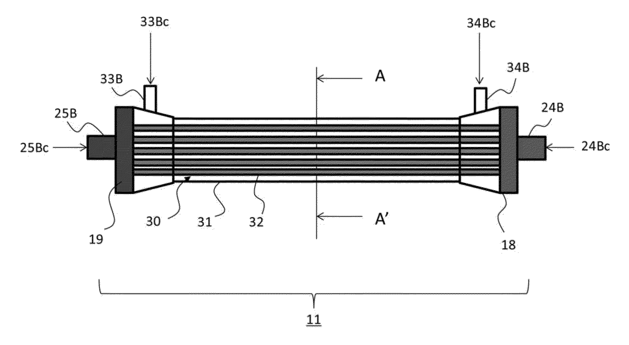
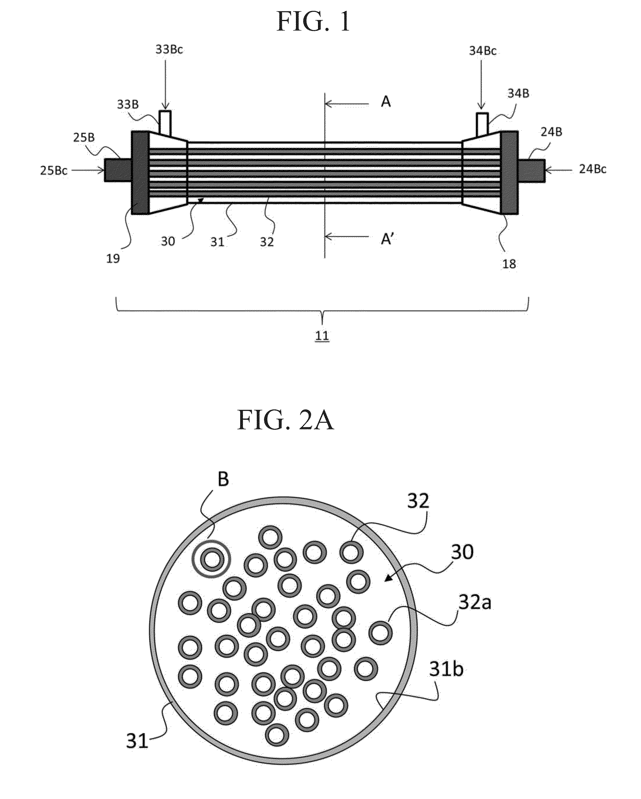
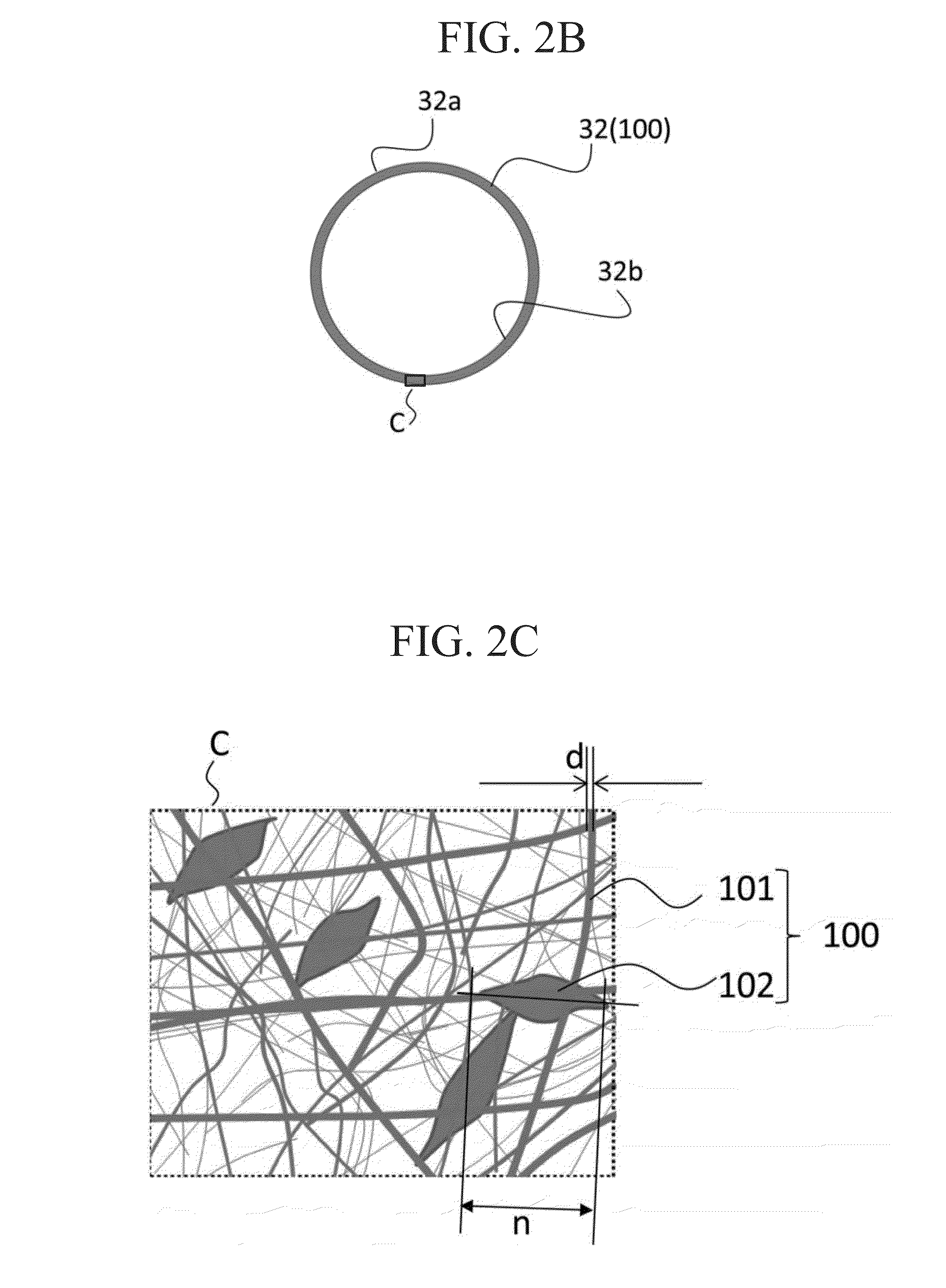
[0057]FIG. 1 is a schematic diagram showing an example of the dialysis device according to the first embodiment. FIG. 2A is a cross sectional view taken along the plane A (line A-A′) in FIG. 1. FIG. 2B is an enlarged view of a portion B in FIG. 2A. FIG. 2C is an enlarged view of a portion C in FIG. 2B.

[0058]As shown in FIG. 1, a dialysis device 11 is mainly configured by including a cylinder 31, a plurality of thin cylinders 32, a first lid portion 18, and a second lid portion 19. The plurality of thin cylinders 32 are loaded in the cylinder 31 by aligning the axial direction. The first lid portion 18 closes the first end side of the cylinder 31. The second lid por...

second embodiment

Dialysis Device

[0104]Next, a dialysis device according to a second embodiment of the present invention will be described.

[0105]FIG. 8 is a schematic diagram showing a dialysis device according to the present embodiment. FIG. 9A is a cross sectional view taken along the line H-H′ in FIG. 8. FIG. 9B is an enlarged view of a portion I in FIG. 9A.

[0106]As shown in FIG. 8, a dialysis device 12 is mainly configured by including a cylinder 131, a plurality of thin cylinders 132, a first lid portion, and a second lid portion 119. The plurality of thin cylinders 132 are loaded in the cylinder 131 by aligning the axial direction. The first lid portion 118 closes the first end side of the cylinder 131, and the second lid portion 119 closes the second end (other end) side of the cylinder 131.

[0107]A first tube joint portion 124B is provided in the first lid portion 118, and a second tube joint portion 125B is provided in the second lid portion 119.

[0108]A first opening 124Bc of the first tube j...

third embodiment

Dialysis Device

[0113]Next, a dialysis device according to a third embodiment of the present invention will be described.

[0114]FIG. 10A is a front schematic view showing a dialysis device 13 according to the present embodiment. FIG. 10B is an enlarged view of a cross section taken along the line J-J′ in FIG. 10A.

[0115]As shown in FIG. 10A, a dialysis device 13 is mainly configured by including a cylinder 231, a plurality of thin cylindrical portions 232, a first lid portion 218, and a second lid portion 219. The plurality of thin cylindrical portions 232 are loaded in the cylinder 231 by aligning the axial direction. The first lid portion 218 closes the first end side of the cylinder 231. The second lid portion 219 closes the second end (other end) side of the cylinder 231.

[0116]A first tube joint portion 224B is provided in the first lid portion 218, and a second tube joint portion 225B is provided in the second lid portion 219.

[0117]An opening 224Bc of the first tube joint portion ...


PUM

PropertyMeasurementUnit
Thicknessaaaaaaaaaa
Diameteraaaaaaaaaa
Diameteraaaaaaaaaa

Abstract

A blood purification membrane capable of adsorbing creatinine which is a uremic toxin in the blood and purifying the blood, the blood purification membrane including fibers and particles adhered to the aforementioned fibers, wherein the aforementioned fibers are composed of a polymer insoluble in water, the aforementioned particles contain SiO2 and Al2O3, and pores capable of incorporating at least a portion of the aforementioned uremic toxin are provided in the aforementioned particles.

Description

TECHNICAL FIELD[0001]The present invention relates to a blood purification membrane, a method for manufacturing a blood purification membrane, and a dialysis device. Priority is claimed on Japanese Patent Application No. 2013-174636, filed Aug. 26, 2013, the content of which is incorporated herein by reference.BACKGROUND ART[0002]As of 2011, in Japan, the number of patients with chronic renal failure has exceeded 300,000 (Non-Patent Document 1). Among them, only less than a few percent of all patients can receive kidney transplants, and the survival of most patients with renal failure depends on the blood purification method, including hemodialysis.[0003]Hemodialysis requires a large amount (equal to or more than 120 L) of water per patient, and electricity to allow the operation of the equipment. For this reason, fully equipped infrastructure facilities of water and electricity are required for the hemodialysis.[0004]Further, for the dialysis patients, the burden in terms of the nu...

Claims


Application Information

Patent Timeline
IPC IPC(8): B01D69/14B29C47/00B01D61/24B01D71/38A61M1/16B01D63/04B01D71/02B29C48/05
CPCB01D69/148B01D63/04B29C47/0014B01D71/028B01D71/38A61M1/16B29L2031/731B01D2325/12B01D2323/39B29K2029/04B29K2031/04B29L2031/14B01D61/243A61K35/14B01D63/02B01D67/0079B01D71/26B01D71/76B01D67/0004B01D69/04B01D69/08B29C48/05A61P13/02A61P7/08B01D71/0281
Inventor EBARA, MITSUHIRONAMEKAWA, KOKIAOYAGI, TAKAO
Owner NAT INST FOR MATERIALS SCI
Why Eureka
Try Eureka