
3-dimensional bioscaffolds

a bioscaffold and 3-dimensional technology, applied in the field of 3-dimensional bioscaffolds, can solve the problems of long and often incomplete healing process, damage to the meniscus, and athletes, especially those who play contact sports, and achieve the effect of decreasing the number of circumferential fibres for each layer progressively

Inactive Publication Date: 2016-07-14
NAT UNIV OF SINGAPORE
View PDF1 Cites 12 Cited by
  • Summary
  • Abstract
  • Description
  • Claims
  • Application Information

AI Technical Summary

Benefits of technology

The invention is about making a scaffold to treat meniscal injuries. The scaffold is made by printing layers of semi-circles and radial fibers on top of each other. The layers are designed to mimic the wedge-shaped meniscus. The more layers that are printed, the fewer the semi-circles there are. The technical effect of this innovation is to provide a better structure for replacing the meniscus in order to restore its function.

Problems solved by technology

The restricted blood supply hinders the regeneration capacity of the fibro-cartilagenous tissue, resulting in a long and often incomplete healing process, which often requires surgery to remove or replace damaged tissue.
Athletes, particularly those who play contact sports, are at risk of meniscal tears.
However, damage to the meniscus can also occur when tissue is weakened as through age in the elderly.
However, the removal of meniscal tissue results frequently in the progressive development of osteoarthritris, involving degradation of joints, including the articular cartilage and sub-chondral bone.
Full or partial meniscectomy has serious drawbacks which have shifted research interest towards the fields of biomaterials and bioengineering.
Creating three-dimensional (3D) bioscaffolds, however, is problematic as cells in culture usually migrate to form a two-dimensional layer and bioscaffolds are required to serve as 3D platforms.
Current methods for creating 3D bioscaffolds such as particle leaching, gas forming, 3D printing or fused deposition modelling produce 3D structures, but they suffer from poor control of inner structure or resolution.
Although tissue engineering methods have developed substantively, current techniques for the repair of meniscus tears or replacement of whole menisci by a tissue-engineered construct using bioscaffolding technologies such as synthetic polymers, hydrogels, ECM components, or tissue-derived materials, even with cell augmentation techniques have yet to yield sustained, reliable long-term results.
Conventional micro-extrusion methods for 3D bioscaffold fabrication are, however, limited by their low resolution.
In addition, the electro-spun meshes are in non-woven form, which are only useful for relatively small number of applications such as filtration.
However, the precise control of each filament orientation is not achieved.
Furthermore, another significant drawback for both the conventional electro-spun meshes and bioscaffolds is the limited pore size, thus resulting in a slow rate of cell propagation.
Although some initial attempts to fabricate 3D polymeric bioscaffolds using NFES have been performed, work has always been limited to 2D patterning due to the difficulty of solvent evaporation, and no 3D structures can be built so far.
Quick solidification of the filaments over a very short distance between the nozzle and collector is normally required to build 3D structures, and this is certainly very challenging for solvent-based process.
However, high temperature is needed to melt the polymers during the fabrication process, thus limiting the application to materials that are temperature-sensitive (i.e. collagen, growth factors etc.) or materials that have high melting points.

Method used

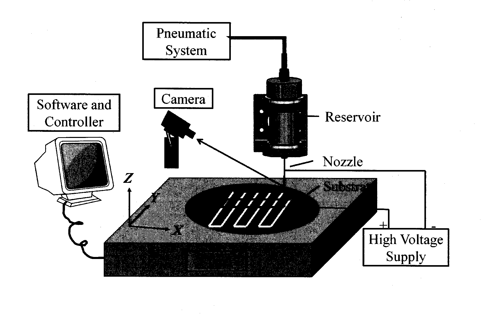
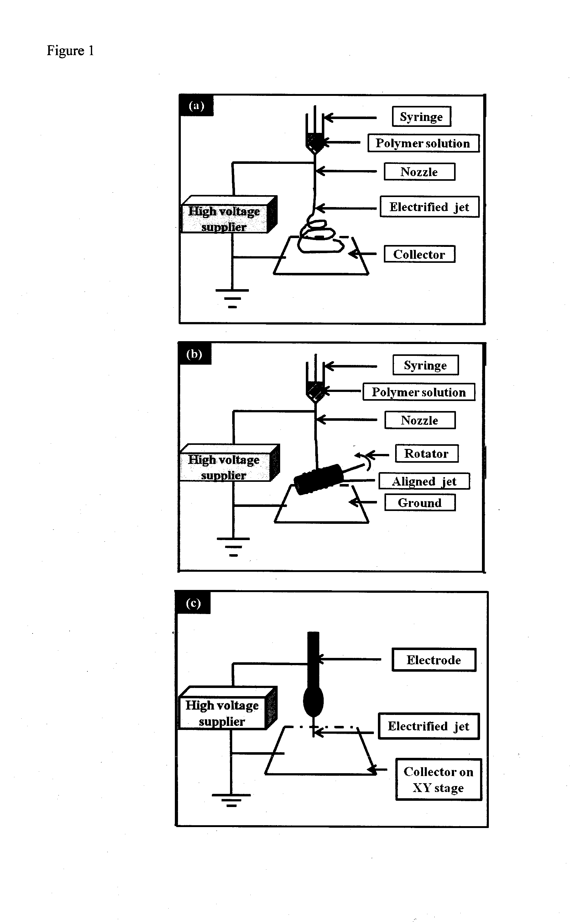
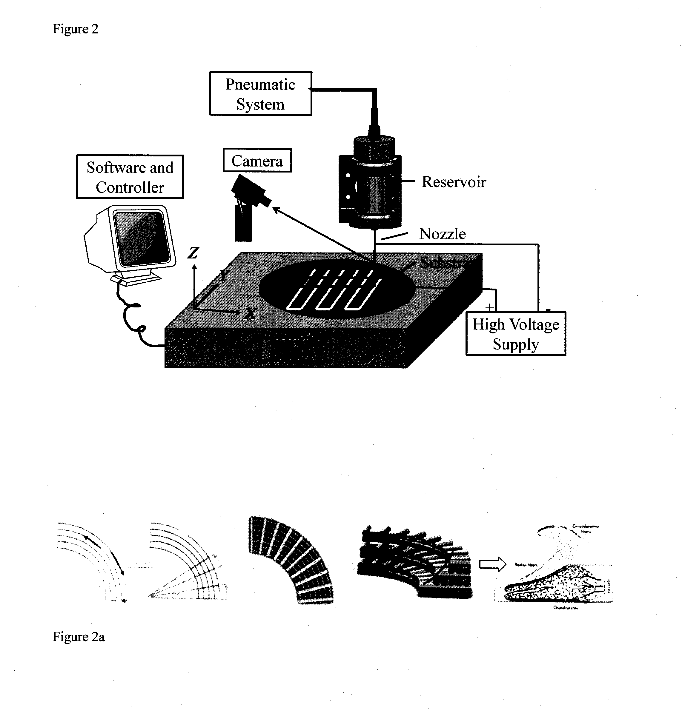

Image

  • 3-dimensional bioscaffolds
  • 3-dimensional bioscaffolds
  • 3-dimensional bioscaffolds

Examples


example 2

Characterization of Bioscaffolds

[0088]SEM examination of the E-jetted PCL filament is shown in FIG. 5a. Parallel filaments were obtained, and the surface of the printed filaments was generally smooth. With the attribution of high voltage, uniform filaments of diameter 20.5±1.9 μm were achieved. It was comparatively smaller than those fabricated using a micro-extrusion system having a filament diameter of 100 μm (Kalita et al. 2003, Wei et al. 2012). Fine filaments have shown to enhance cell attachment and modulate cell signalling pathways, thereby accelerating extracellular matrix production (Nur-E-Kamal et al. 2005, Li et al. 2006).

[0089]As reported in the literature, the pore sizes of electrospun bioscaffolds were relatively small as compared to the size of cells, thus limiting cell penetration into the bioscaffolds (Kidoaki et al. 2005). To evaluate this, a 10-layered bioscaffold was fabricated in this study (FIG. 5b). The pore size obtained was 450±50 μm. The large pore sizes wo...

example 3

In-Vitro Study of Chondrocytes Responses on Bioscaffolds

[0092]After culturing for 3 days, the viability of chondrocytes on the fibrous bioscaffolds was evaluated using live / dead staining. It was observed that there were numerous live chondrocytes (highlighted parts of the image) attaching and spreading on the surfaces of collagen-coated PCL filaments, showing good viability of cells (FIG. 7a). In addition, chondrocytes were seen adhering on the inner surfaces of the bioscaffold, demonstrating good cell infiltration. Some cells were well-focused in plane whilst others were out of focused, implying that these cells were attaching in different layers of the bioscaffold.

[0093]FIG. 7b shows the sGAG production on cell-laden bioscaffolds and control. The amount of sGAG content on each sample increased with culturing time. However, sGAG produced by chondrocytes on bioscaffolds was significantly higher than that of the control at all time points. Results revealed a two-fold increase in sGAG...


PUM

PropertyMeasurementUnit
pressureaaaaaaaaaa
internal diameteraaaaaaaaaa
thicknessaaaaaaaaaa

Abstract

The invention concerns an apparatus and a method for the manufacture of a three-dimensional (3D) bioscaffold; a 3D bioscaffold made using same; and the use of said 3D bioscaffold in the manufacture of an implant to treat injuries such as, but not limited to, meniscal injuries.

Description

FIELD OF THE INVENTION[0001]The invention concerns an apparatus and a method for the manufacture of a three-dimensional (3D) bioscaffold; a 3D bioscaffold made using said method; and the use of said 3D bioscaffold in the manufacture of an implant to treat injuries such as, but not limited to, meniscal injuries.BACKGROUND OF THE INVENTION[0002]The menisci of the knee are two semilunar fibrocartilage discs, located in the knee joint between tibia and femur, improving stability and aiding rotatory movements of the knee, acting as a shock absorber and providing nutrition in the form of synovial fluid to the articular cartilage. In humans meniscal structures are not just found in the knee joint, but are also present in acromioclavicular, sternoclavicular and temporomandibular joints.[0003]The meniscus is typically an avascular structure with the primary blood supply limited to the periphery, the inner part of the meniscus is nourished by the synovial fluid through diffusion. The restrict...

Claims


Application Information

Patent Timeline
Patent Type & Authority Applications(United States)
IPC IPC(8): B29C67/00D01D5/00A61F2/02
CPCB29C67/0055D10B2509/00B29C67/0085D01D5/003A61F2/30756A61F2002/30766A61F2240/001B29K2033/04B29K2105/0073B29L2031/753B29K2995/0056B29K2995/006B33Y10/00B33Y30/00B33Y40/00B33Y80/00D10B2331/04D10B2401/12A61F2/02A61F2/3872A61F2/08A61F2240/002A61F2/3094A61L27/18A61L27/50A61L27/56A61L2430/06B29C64/245B29C64/209B29C64/118B29C64/255B29C64/106C08L67/04
Inventor THIAN, ENG SANFUH, YING HSI JERRYSUN, JIEWANG, EN JEN WILSONHONG, GEOK SOONWONG, YOKE SANLI, JINLANGUO, YILIN
Owner NAT UNIV OF SINGAPORE
Learn More