Shear spun sub-micrometer fibers

a technology of sub-micrometer fibers and spun fibers, applied in the direction of textiles and paper, filament/thread forming, non-woven fabrics, etc., can solve problems such as inacceptable methods

Active Publication Date: 2016-07-21
SHPP GLOBAL TECH BV
View PDF2 Cites 2 Cited by
  • Summary
  • Abstract
  • Description
  • Claims
  • Application Information

AI Technical Summary

Problems solved by technology

This has been a barrier to the introduction and testing of many of these resins suitability for use in these applications.
Electro-spinning of all of these resins is possible, but the cost of the resin and the slow throughput rate of this process have made this method unacceptable.

Method used


Image

  • Shear spun sub-micrometer fibers
  • Shear spun sub-micrometer fibers
  • Shear spun sub-micrometer fibers

Examples


examples 1-5

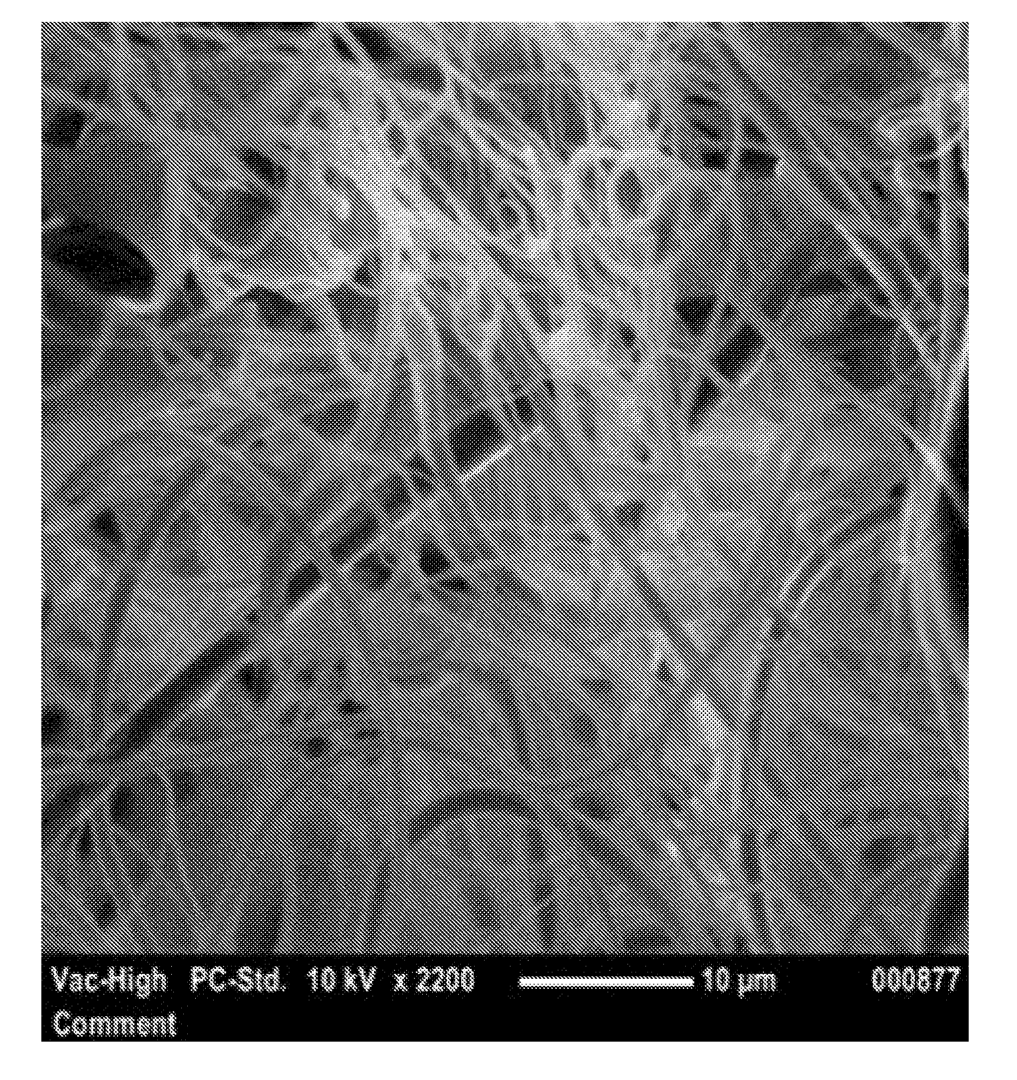
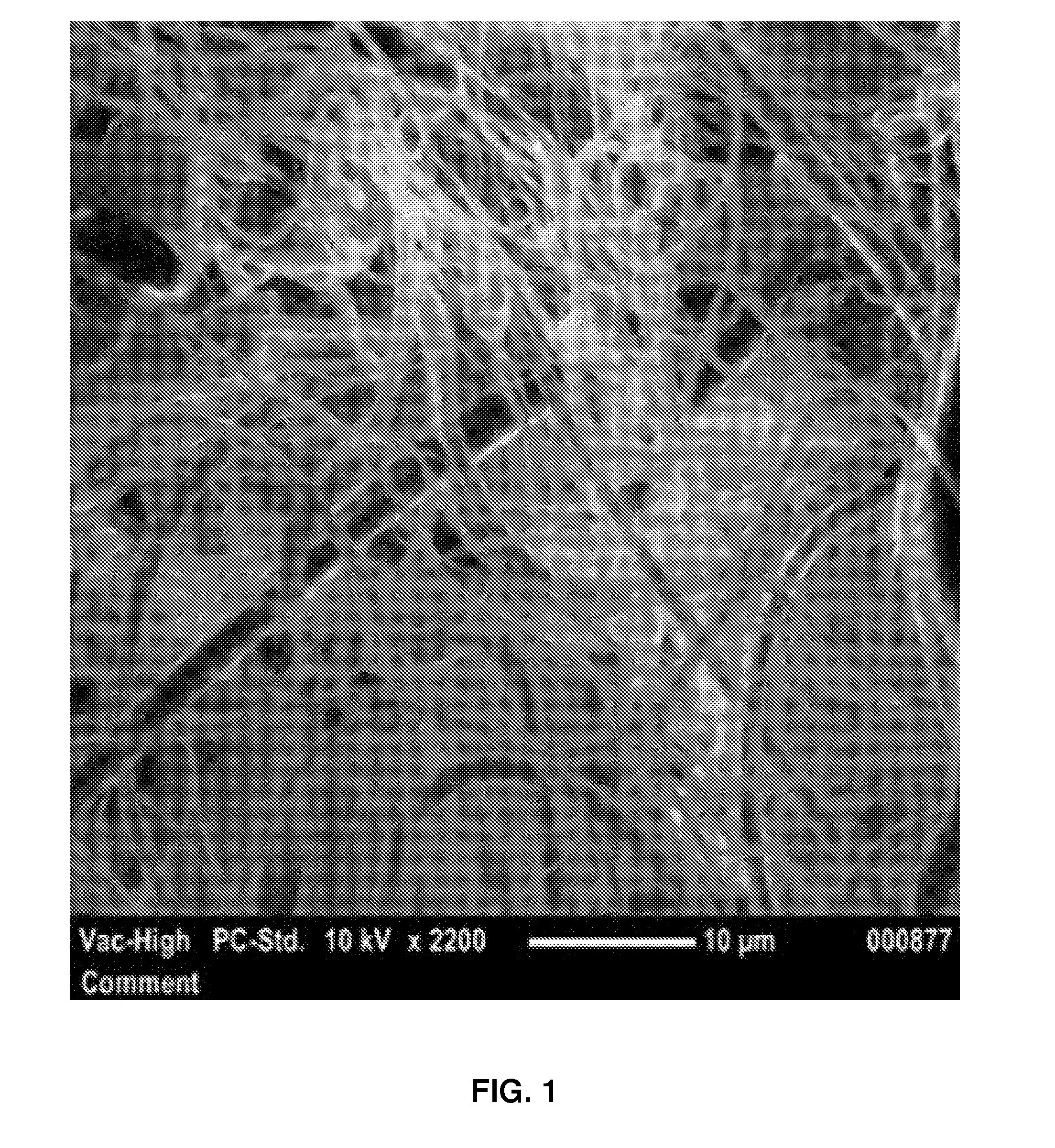
[0076]Several variations of PEI resins were solution spun to average fiber diameters in the sub-micrometer range. FIG. 1 is an exemplary image of the fibers obtained. Table 1 provides a list of materials employed in Examples 1-5.

TABLE 1ComponentChemical DescriptionSourcePEIpolyetherimideULTEM(TM), SABICGlycerolGlycerol (99.7%)Brenntag Southwest, Inc.EthanolEthanol (Anhydrous ACS / USPPharmaco-Aapergrade, 99.5%)ChloroformChloroform (99+%, extra pure,Acros Organicsstabilized with ethanol)

[0077]Distributions of fiber diameters were measured by imaging the sample using a scanning electron microscope (SEM) (e.g., Phenom Pro Desktop SEM). A minimum magnification of 140× was used. A minimum of 4 images are retained for fiber diameter analysis. Fiber diameter analysis software (e.g., Fibermetric software) is used to measure the sample's images and at least 50 measurements per image, which are randomly selected by the software, are used in determining the average fiber diameter and distributio...

example 1

[0078]A solution (first dispersion medium) comprising of 15% ULTEM™ 1010 polyetherimide dissolved in chloroform, with a solution viscosity of about 500 cP, was injected into an anti-solvent (second dispersion medium) comprised of about 60% glycerol, about 25% ethanol and about 15% water flowing at a rate of 5 ml / min. This sample was produced using a Xanofi Xanoshear™ spinning system. The example resulted in fibers with a diameter between 165 nm and 9.5 pm with an average diameter of 3.7 μm. FIG. 3A represents the fiber morphology of the sample. FIG. 3B is a histogram of the fiber diameter measurements taken.

example 2

[0079]A solution (first dispersion medium) comprising of 15% ULTEM™1010 polyetherimide dissolved in chloroform, with a solution viscosity of about 500 cP, was injected into an anti-solvent (second dispersion medium) comprised of about 70% glycerol, about 17.5% ethanol and about 12.5% water flowing at a rate of 15 ml / min. This sample was produced using a Xanofi Xanoshear™ spinning system. The example resulted in fibers with a diameter between 400 nm and 5.8 μm with an average diameter of 2.1 μm. FIG. 4A represents the fiber morphology of the sample. FIG. 4B is a histogram of the fiber diameter measurements taken.


PUM

PropertyMeasurementUnit
diameteraaaaaaaaaa
widthaaaaaaaaaa
viscosityaaaaaaaaaa

Abstract

A process including shearing a first dispersion medium and a second dispersion medium under conditions that precipitate a plurality of polymeric fibers; and collecting the plurality of polymeric fibers at a rate of at least 300 grams / hour. The first dispersion medium is a solution including at least one polymeric component. The at least one polymeric component includes a poly-etherimide component selected from the group consisting of polyetherimide homopolymers, polyetherimide co-polymers, poly etherether ketones homopolymers, polyetherether ketones copolymers, polyphenylene sulfones homopolymers, polyphenylene sulfones copolymers, and combinations thereof. Products produced by the process can be non-woven paper, medical implants, ultra-fine filters, membranes, hospital gowns, electrical insulation paper, honeycomb structures and personal hygiene products, dialyzers, blood, oxygenator filters, intravenous (IV) filters, diagnostic test filters, and blood / apheresis filters.

Description

BACKGROUND OF THE INVENTION[0001]The invention relates generally to shear spun sub-micrometer fibers and more specifically to shear spun sub-micrometer polymeric fibers.[0002]Polyetherimide (PEI) fibers are used in many applications and composite structures that require various unique properties of the different resins to perform in the necessary environment. Many of these applications require the resins to be in a fiber size much smaller than currently achievable using conventional methods of fiber production at a reasonable throughput rate. This has been a barrier to the introduction and testing of many of these resins suitability for use in these applications. PEI has been converted into fibers using the melt spinning process for some time. Such processes are capable of producing fibers in the range of 10-20 micrometers. Melt blowing has also been attempted with PEI, and there is currently work being done to make this process amenable to using PEI. If the technical hurdles could ...

Claims


Application Information

Patent Timeline
Patent Type & Authority Applications(United States)
IPC IPC(8): D01D5/40D04H1/40D04H1/46
CPCD01D5/40D04H1/40D04H1/46B29B9/10
Inventor PETERS, RICHARDLABELLE, JACOB SCOTTTEUTSCH, ERICH
Owner SHPP GLOBAL TECH BV
Why Eureka
Try Eureka