Device for the diagnosis of the operability of a particle filter for an exhaust gas stream of an internal combustion engine

a technology of particle filter and internal combustion engine, which is applied in the direction of dispersed particle filtration, exhaust treatment, chemical analysis using catalysis, etc., can solve the problems of reducing the flow of exhaust gas through the portion of clogging of the pipe, and the temperature of exhaust gas in the branch pipe downstream of the detection filter goes down, so as to facilitate the manufacture of the device, facilitate the integration into the exhaust line, and facilitate the integration into the existing exhaus

Inactive Publication Date: 2016-07-28
BOSAL EMISSION CONTROL SYST
View PDF2 Cites 5 Cited by
  • Summary
  • Abstract
  • Description
  • Claims
  • Application Information

AI Technical Summary

Benefits of technology

[0035]The afore-mentioned aspects of the device according to the invention have a number of advantages. One advantage is the ease to manufacture of the device. The device is easier to integrate into an exhaust line as no additional outside space is required. This also has the advantage of being capable to be readily integrated into an existing exhaust line without modification of the car body space around the device. Additionally, the device according to the invention is less sensitive for ambient conditions like drive wind and less prone to tampering as the outside of the device has the shape related to a normal exhaust line. Another advantage of the device according to the invention is the cheaper manufacture and even low cost and simple construction of the device when compared to existing devices. A further advantage is the spontaneous regeneration of the detection filter which may be performed independently from the regeneration of the main particle filter. Another advantage are shorter intervals between checks of the detection filter and hence more frequent checks on the leakage rate of the main particle filter and increasing the monitoring frequency.
[0036]Additionally the device may be embodied such that the detection filter is accessible from the exterior of the exhaust conduit for easy maintenance and replacement without having to disassemble the device. In particular, the detection filter is insertable through a slit in the wall of the exhaust chamber, the slit opening towards the exterior of the exhaust conduit. Alternatively, the device may be embodied such that the exhaust chamber is removable from the exterior of the exhaust conduit without having to remove the entire device from the vehicle, and the detection filter may be replaced from the removed exhaust chamber. After replacement of the filter, or maintenance of the exhaust chamber, the exhaust chamber is introduced back into the device.
[0037]After sales serviceability is also increased with the device according to the invention and presents easy accessibility for maintenance.
[0038]It may be advantageous to arrange the detection filter such that the cross-section of the detection filter is arranged at least partly, particularly completely, within the virtual bounding tubular envelope. The particular arrangement of the detection filter allows for an exposure of the detection filter to the hot exhaust gases at least around the detection filter, thereby being able to reach sufficiently high temperatures for regeneration even when the detection filter is at least partly clogged, resulting in reduced (hot) exhaust gas flow through the detection filter. The detection filter may be located close to the particulate filter (particularly within a range of from 1 cm to 100 cm from the back face of the particulate filter) in order to enhance regeneration of the detection filter, either by an active regeneration process or by a spontaneous regeneration.

Problems solved by technology

In case there are too many residual particles contained in the exhaust gas that has passed through the particle filter, the detection filter in the secondary exhaust line (branch pipe) is getting clogged, this clogging of the detection filter resulting in a reduced flow of exhaust gas through the portion of the branch pipe downstream of the detection filter.
The more soot particles are contained in the exhaust gas having passed the particle filter (i.e. the worse the particle filter works) the more the detection filter in the branch pipe is getting clogged, and the more the temperature of the exhaust gas in the branch pipe downstream of the detection filter goes down.
While this principle generally works well, one of the major drawbacks of the above-discussed constructional approach (branch pipe arranged at a distance to main pipe) is that no compact construction is possible as the secondary exhaust line is arranged outside of the perimeter of the main exhaust line.
Additionally, the bent portions of the branch pipe (the inlet and outlet of the branch pipe are connected to the main pipe) are difficult and expensive to manufacture thus rendering the device shown in US 2013 / 0047841 A1 impractical.

Method used


Image

  • Device for the diagnosis of the operability of a particle filter for an exhaust gas stream of an internal combustion engine
  • Device for the diagnosis of the operability of a particle filter for an exhaust gas stream of an internal combustion engine
  • Device for the diagnosis of the operability of a particle filter for an exhaust gas stream of an internal combustion engine

Examples


first embodiment

[0054]FIG. 1-4 depict a first embodiment according to the present invention.

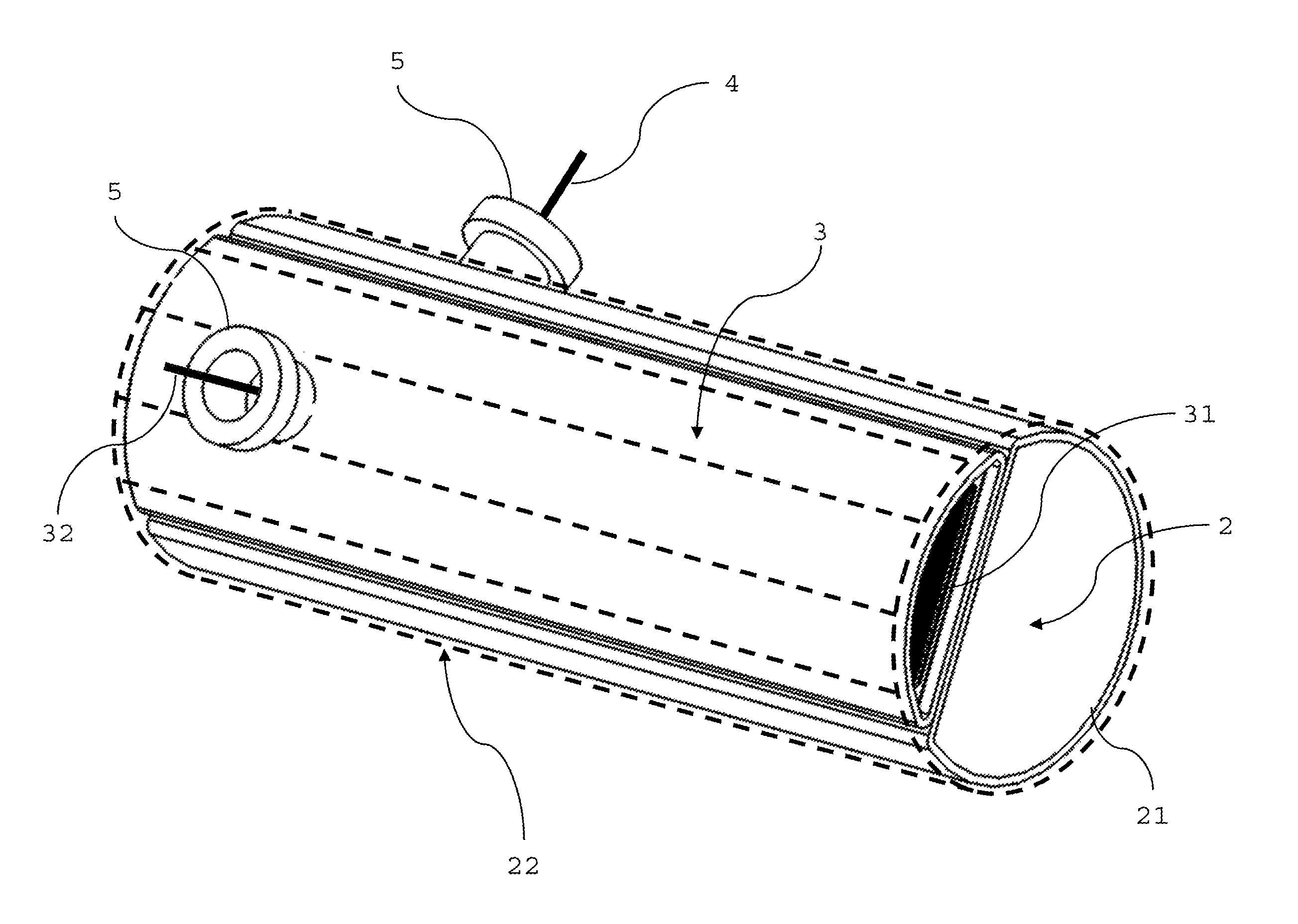
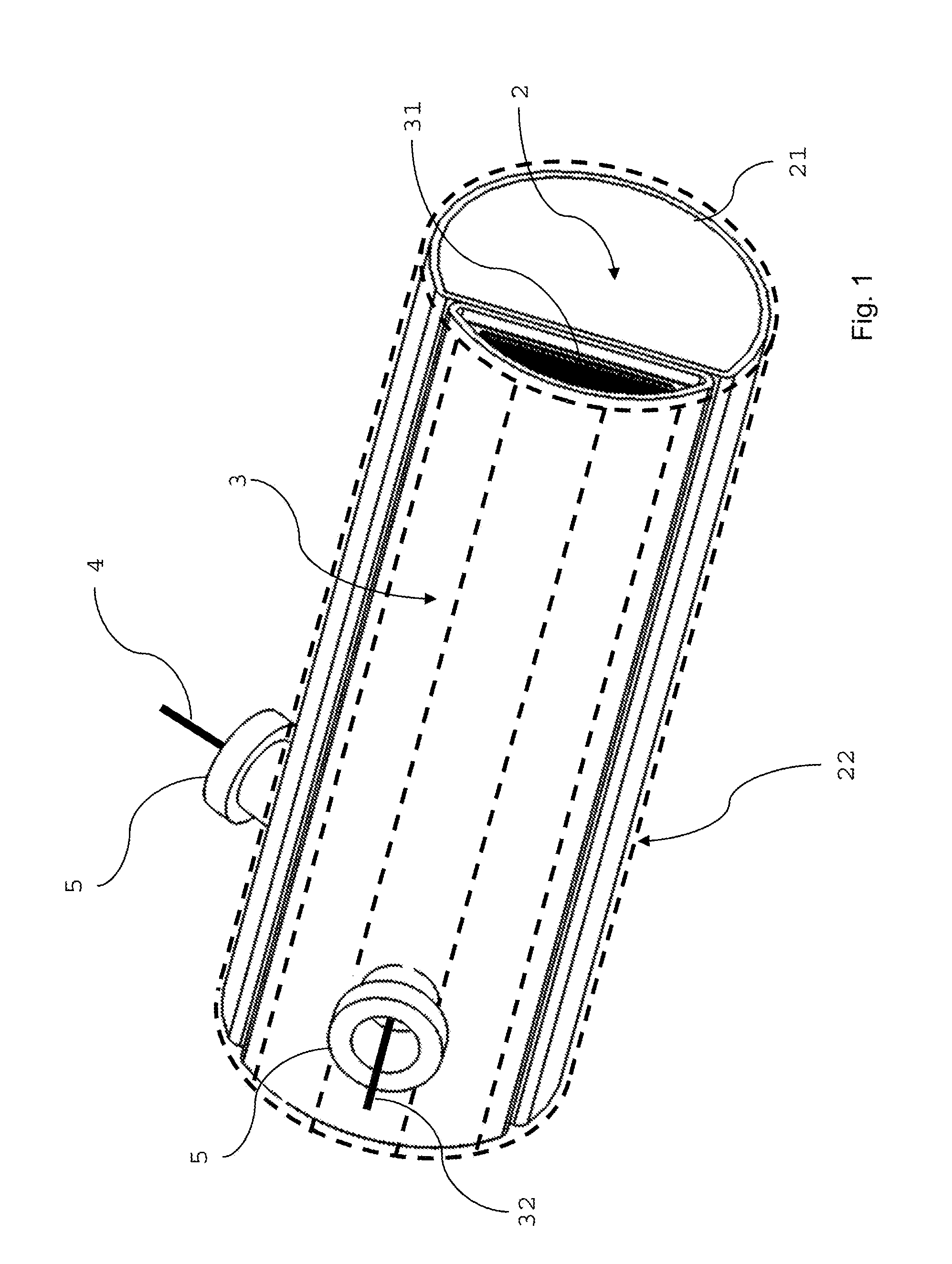
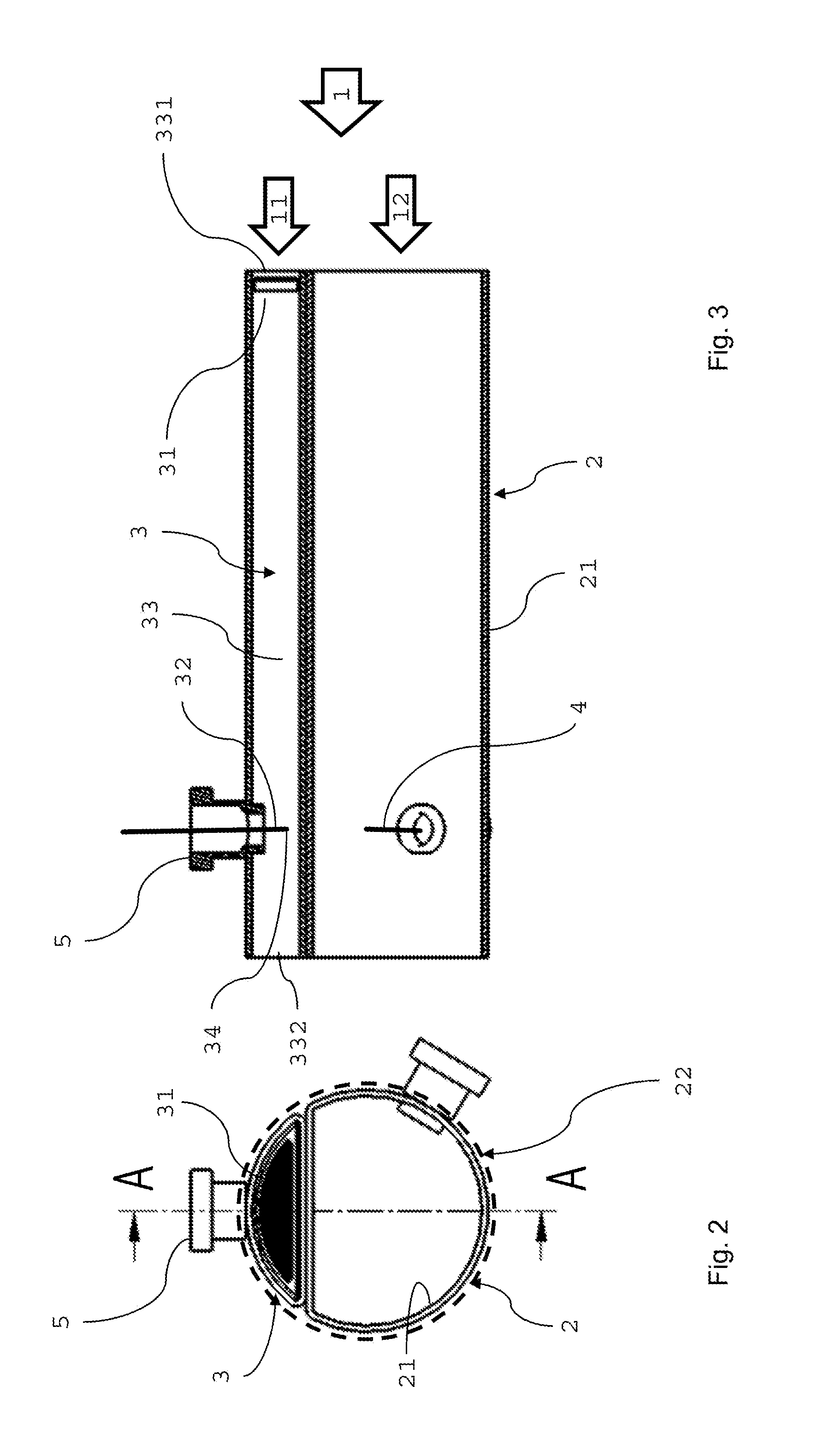
[0055]In FIG. 1, an exterior view of an embodiment of the device for the diagnosis of the operability of a particle filter for an exhaust gas stream 1 of an internal combustion engine is represented with an exhaust conduit 2 having an outer wall 21. The exhaust conduit 2 is flattened on one side. The outer wall 21 of the exhaust conduit 2 defines a virtual bounding cylinder 22, which is a particular case of the virtual bounding tubular envelope, the virtual bounding cylinder 22 being the smallest possible cylinder having a circular cross-section and a cylinder axis normal to the cross-section of the exhaust conduit 2 and completely surrounding the outer wall 21 of the exhaust conduit 2. In the particular embodiment shown in FIG. 1, the exhaust conduit 2 has a circular cross-section flattened on one side, but may have any geometry suitable for an exhaust conduit. The device further comprises an exhaust chambe...

second embodiment

[0066]FIG. 5-8 depict a second embodiment according to the present invention.

[0067]FIG. 5 represents a further specific embodiment of the present invention. The entire exhaust chamber 3 is arranged in the interior of the exhaust conduit 2 having a cylindrical shape with a circular cross-section. In the particular embodiment shown in FIG. 5, the exhaust conduit 2 has a circular cross-section, but may have any geometry suitable for an exhaust conduit. Alternatively, the exhaust chamber 3 is only partly arranged in the interior of the exhaust conduit 2 over the entire length of the exhaust chamber 3 and a portion of the exhaust chamber 3 may surpass the outside wall 21 of the exhaust conduit 2.

[0068]A heat sink body 5 is contacting the exhaust chamber 3 for increased thermal energy exchange with the environment exterior to the exhaust conduit 2.

[0069]A detection filter 31 is insertable through a slit into the exhaust chamber 3 and is accessible from the exterior of the exhaust chamber ...

third embodiment

[0075]FIG. 9-11 depict a third embodiment according to the present invention.

[0076]FIG. 9 shows an additional specific embodiment of the present invention. In this embodiment, the entire exhaust chamber 3 is arranged in the interior of the exhaust conduit 2 having a cylindrical shape with a circular cross-section. The exhaust conduit 2 may however have any geometry suitable for an exhaust conduit. A detection filter 31 is located at the inlet 331 of the exhaust chamber 3. The heat sink body 5 comprises exterior fins 51 for better thermal energy exchange with the environment exterior to the exhaust conduit 2.

[0077]The device may be embodied such that the exhaust chamber is removable from the exterior of the exhaust conduit, for example through a screw connection, without having to remove the entire device from the vehicle, and the detection filter may be replaced from the removed exhaust chamber. After replacement of the filter, or maintenance of the exhaust chamber, the exhaust cham...


PUM

PropertyMeasurementUnit
temperatureaaaaaaaaaa
lengthaaaaaaaaaa

Abstract

A device for the diagnosis of the operability of a particle filter for an exhaust gas stream of an internal combustion engine, the device comprising:an exhaust conduit having an outer wall, the outer wall of the exhaust conduit defining a virtual bounding tubular envelope, the virtual bounding tubular envelope being the smallest possible tubular envelope having a circular cross-section co-planar to the cross-section of the exhaust conduit and completely surrounding the outer wall of the exhaust conduit at any position along the exhaust conduit,an exhaust chamber having a detection filter,a temperature sensor arranged in the exhaust chamber, the temperature sensor being arranged for measuring the temperature of a portion of the exhaust gas stream having passed through at least a part of the detection filter,wherein at least a portion of the exhaust chamber is thermally connected to the environment exterior to the exhaust conduit, andwherein the exhaust chamber is at least partly arranged within the virtual bounding tubular envelope over the entire length of the exhaust chamber.

Description

[0001]This application claims benefit of Serial No. 15152510.2, filed on 26 Jan. 2015 in the European Patent Office and which application is incorporated herein by reference. To the extent appropriate, a claim of priority is made to the above disclosed application.FIELD OF THE INVENTION[0002]The invention relates to a device for the diagnosis of the operability of a particle filter for an exhaust gas stream of an internal combustion engine device.BACKGROUND[0003]In order to comply with more and more strict legislature related to the protection of the environment, reduction of environmental pollution through automotive vehicles with internal combustion engines is crucial. Therefore, in particular the exhaust systems of vehicles with diesel engines comprise particle filters designed to drastically reduce or eliminate soot particles in the exhaust gas finally emitted from the exhaust system to the environment. To ensure that these particle filters properly work so-called “On-Board-Diag...

Claims


Application Information

Patent Timeline
Patent Type & Authority Applications(United States)
IPC IPC(8): G01M15/10G01N31/10F01N3/021B01D46/00F01N13/00F01N11/00
CPCG01M15/102F01N13/008F01N11/00F01N2550/04B01D46/0086G01N31/10F01N2560/06F01N3/0211F01N11/002F01N3/021F01N2410/00F01N2470/00F01N2560/05F01N13/0093Y02T10/12Y02T10/40
Inventor CLOUDT, ROBERTWOLLANTS, FREDDY
Owner BOSAL EMISSION CONTROL SYST
Why Eureka
Try Eureka