Akinetic swept laser apparatus and method for fast sweeping of the same

a technology of kinetic swept laser and swept laser, which is applied in the direction of electrical equipment, laser details, active medium shape and construction, etc., can solve the problems of limited tunability of methods, limited reliability, and complex buffering, and achieves faster sweeping speed and power output. higher

Active Publication Date: 2016-08-04
UNIVERSITY OF KENT
View PDF2 Cites 7 Cited by
  • Summary
  • Abstract
  • Description
  • Claims
  • Application Information

AI Technical Summary

Benefits of technology

[0011]In a first aspect, the present invention discloses a method and apparatuses to implement an akinetic swept source that can operate at a much faster sweeping speed, with considerable higher power output.

Problems solved by technology

However, the reliability of Fabry-Perot and the complexity of buffering limit the applicability of such principles.
The filters mentioned above are based on mechanical movement of parts which limits their reliability.
This method has limited tunability, due to the significant decrease in output power when driving it at high frequency repetition rates.

Method used


Image

  • Akinetic swept laser apparatus and method for fast sweeping of the same
  • Akinetic swept laser apparatus and method for fast sweeping of the same
  • Akinetic swept laser apparatus and method for fast sweeping of the same

Examples


examples

[0071]In continuation, examples of the present invention will be described.

first example

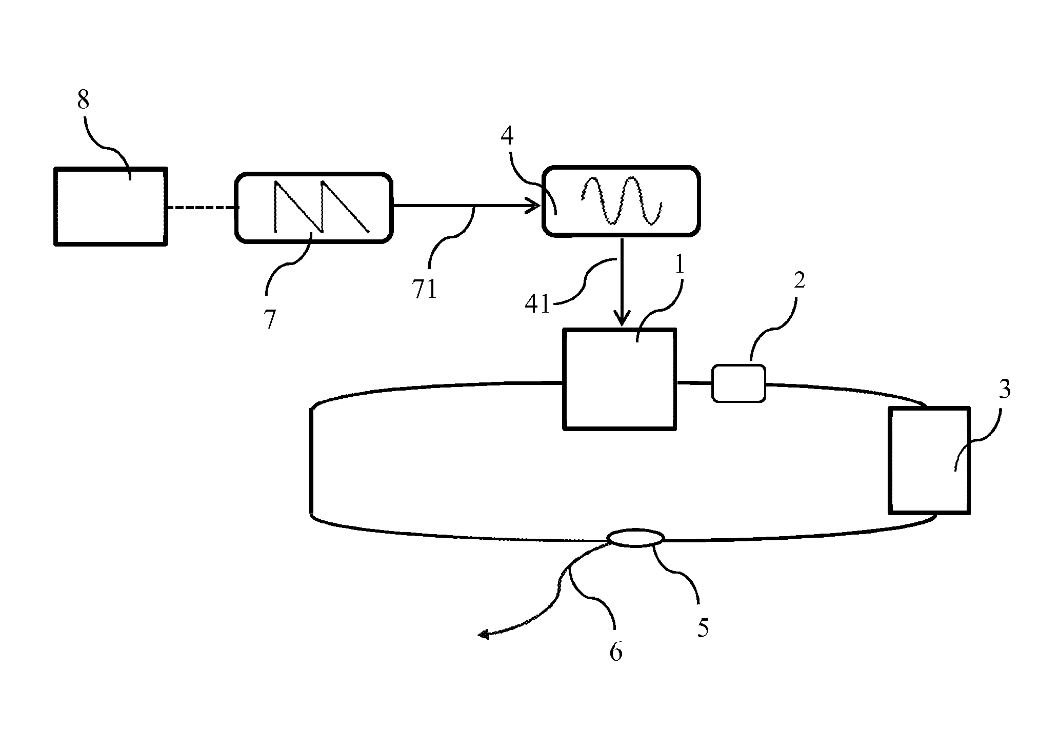
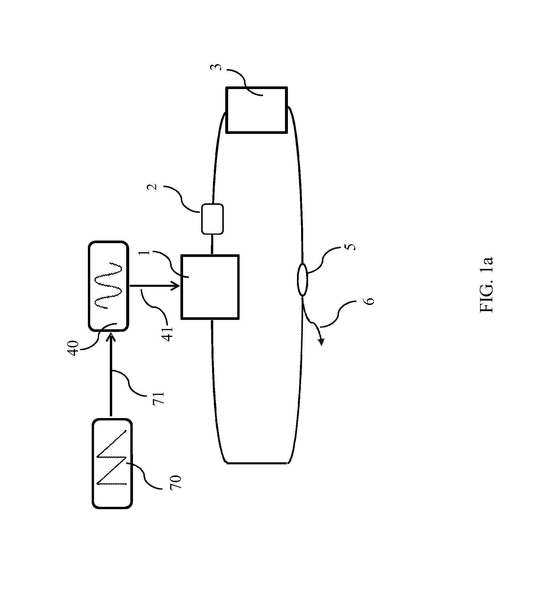
[0072]FIG. 5 illustrates the embodiment of an akinetic swept laser according to the third aspect of the invention. A fibre ring laser configuration is employed, where the functions of both mode-locking mechanism block (nonlinear medium) 1 and optical amplifier 2 are accomplished by a semiconductor optical amplifier (SOA), 1, 2 according to the present invention. The SOA 1, 2 is placed in a ring delimited by fiber optic isolators (optional) 51, which ensure unidirectional lasing, together with dispersion means 3 implemented using a dispersion compensating fiber (DCF), 3a. The RF signal 41 is applied to the SOA 1, 2 via a radio frequency input 80 (bias tee). The output optical emission is drawn out through splitter 5, a single mode coupler of 10 / 90, with 10% extracted out of the cavity. The semiconductor optical amplifier 52 is of similar type of device as the gain medium 1, 2, but of larger dBm power value.

[0073]As a practical implementation, a SOA, 1, 2, type SOA-L-C-14-FCA, BT CIP ...

second example

[0087]In the second example, the operation of the basic ring cavity swept laser, as shown in FIG. 12 will be illustrated with a different dispersion means. This comprises an assembly containing the following elements: an optical circulating device 52 and a chirped fibre Bragg grating (cFBG), 3b. According to FIG. 12, the embodiment uses a semiconductor optical amplifier (SOA) as gain medium 1, 2, modulated by a large frequency deviation VCO 4 driven by large frequency sweeping generator 7. A SOA, 1, 2, is delimited by two fiber optic isolators, 51, to ensure unidirectional lasing. The RF signal 41 is applied to the SOA 1, 2 via a radio frequency input 80 (bias tee). A controller 8 is used to drive the sweeping generator 7. The controller 8 is instructed by three parameters: fR, δf and b.

[0088]As a particular example, a system according to FIG. 12 was assembled, operating at 1060 nm, using a SOA (QPhotonics-1050) with a maximum current 300 mA and a bandwidth larger than 100 nm. A cF...


PUM


Abstract

The present invention discloses a method and apparatus for producing a narrow line laser emission that can be tuned at frequency rates exceeding 100 kHz. The laser apparatus is capable of fast scanning speeds close to multiples of the cavity resonance frequency. The laser cavity can be either a ring or a line resonator. This comprises dispersive means and a nonlinear medium, whose parameter when modulated induces mode-locking, referred from now on as a mode-locking mechanism block, an optical amplifier used as a gain medium and a splitter that ensures that a certain percentage of the laser emission from the gain medium is tapped outside the cavity. The driving method is accomplished with an electronic mechanism that includes a controller drive sweeping generator and a voltage controlled oscillator that injects a tunable radio frequency signal into the nonlinear mode-locking mechanism block. In particular, a semiconductor amplifier can accomplish both functions of amplification and mode-locking, by driving it with RF signals. Two resonant mechanisms are employed to modulate in frequency the mode-locking mechanism block (usually the optical gain in a semiconductor amplifier) and to achieve high frequency tuning rates. The configuration is compatible with working at sweeping rates close to multiples of the cavity resonance frequency as well as with buffering for increased tuning speeds.

Description

FIELD OF THE INVENTION[0001]The present invention relates to a tunable laser and to a driving method of the same laser.BACKGROUND AND PRIOR ART[0002]The method mostly accepted today for optical coherence tomography (OCT) is based on sweeping the frequency of a narrow band laser, usually termed as a swept source. Several principles of sweeping the laser emission have been developed. The most common principle employed is that of a spectral filter in a closed loop, where the tunable laser apparatus uses a Fabry-Perot filter, as disclosed in Patent Document 1 (US 2003 / 6538748 B1), a polygon filter, as disclosed in Patent Document 2 (US 2009 / 7489713 B2), or a micro electrical mechanical scanning (MEMS) filter, as disclosed in Patent Document 3 (US 2012 / 8275008 B2). Commercial vendors exist, such as Axsun and Santec, companies using MEMS filters. Such filters limit the tuning to several hundreds of kHz. In Non-Patent Document 1 (R. H. Huber et al, “Fourier domain mode-locking (FDML): A ne...

Claims


Application Information

Patent Timeline
Patent Type & Authority Applications(United States)
IPC IPC(8): H01S3/11H01S3/067H01S3/10
CPCH01S3/1109H01S3/06791H01S3/10007H01S3/08009H01S3/08013H01S5/0657H01S5/146
Inventor PODOLEANU, ADRIANSTANCU, RADU-FLORIN
Owner UNIVERSITY OF KENT
Why Eureka
Try Eureka