Combined gain-soa chip

Active Publication Date: 2016-08-11
FRAUNHOFER GESELLSCHAFT ZUR FOERDERUNG DER ANGEWANDTEN FORSCHUNG EV
View PDF0 Cites 0 Cited by
  • Summary
  • Abstract
  • Description
  • Claims
  • Application Information

AI Technical Summary

Benefits of technology

[0005]According to an embodiment, a combined Gain-SOA Chip for forming a hybrid laser by a combination with an external reflector may have: a gain section configured to achieve a light gain within a laser cavity formed by a combination with the external reflector, an SOA section configured to amplify light coupled out of the laser cavity, and an optical grating arranged between the gain section and the SOA section so as to form an end of the laser cavity facing the SOA section, and to achieve the coupling of the light out of the laser cavity. Accordingly, only a single chip has to be hybrid integrated in a tunable laser in order to achieve high output powers, which significantly redu

Problems solved by technology

However, as the gap width strongly influences the optical coupling losses between the gain and SOA section, very narrow g

Method used


Image

  • Combined gain-soa chip
  • Combined gain-soa chip
  • Combined gain-soa chip

Examples


Example

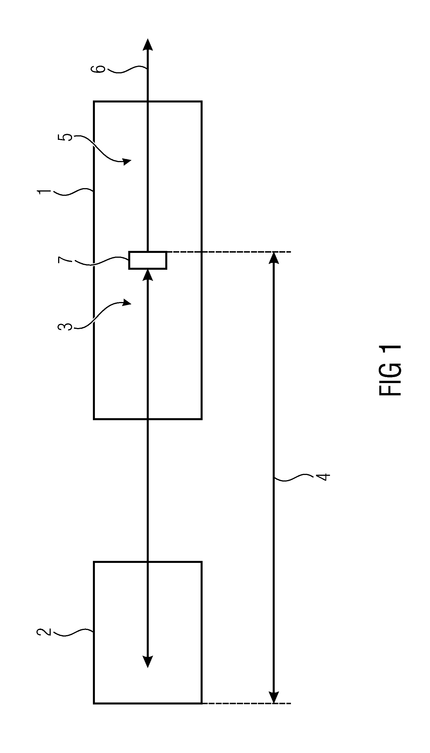
[0036]FIG. 1 shows a combined Gain-SOA Chip 1 for forming a hybrid laser by a combination with an external reflector 2. The combined Gain-SOA Chip 1 comprises a gain section 3 and an SOA section 5.

[0037]The gain section 3 is configured to achieve a light gain within a laser cavity 4, which laser cavity 4 is formed by a combination with the external reflector 2.

[0038]The SOA section 5 is configured to amplify light 6 that is coupled out of the laser cavity 4.

[0039]An optical grating 7 is arranged between the gain section 3 and the SOA section 5. The optical grating 7 forms an end of the laser cavity 4 which end faces the SOA section 5. Furthermore, said end of the laser cavity 4 is configured to achieve the coupling of the light 6 out of the laser cavity 4.

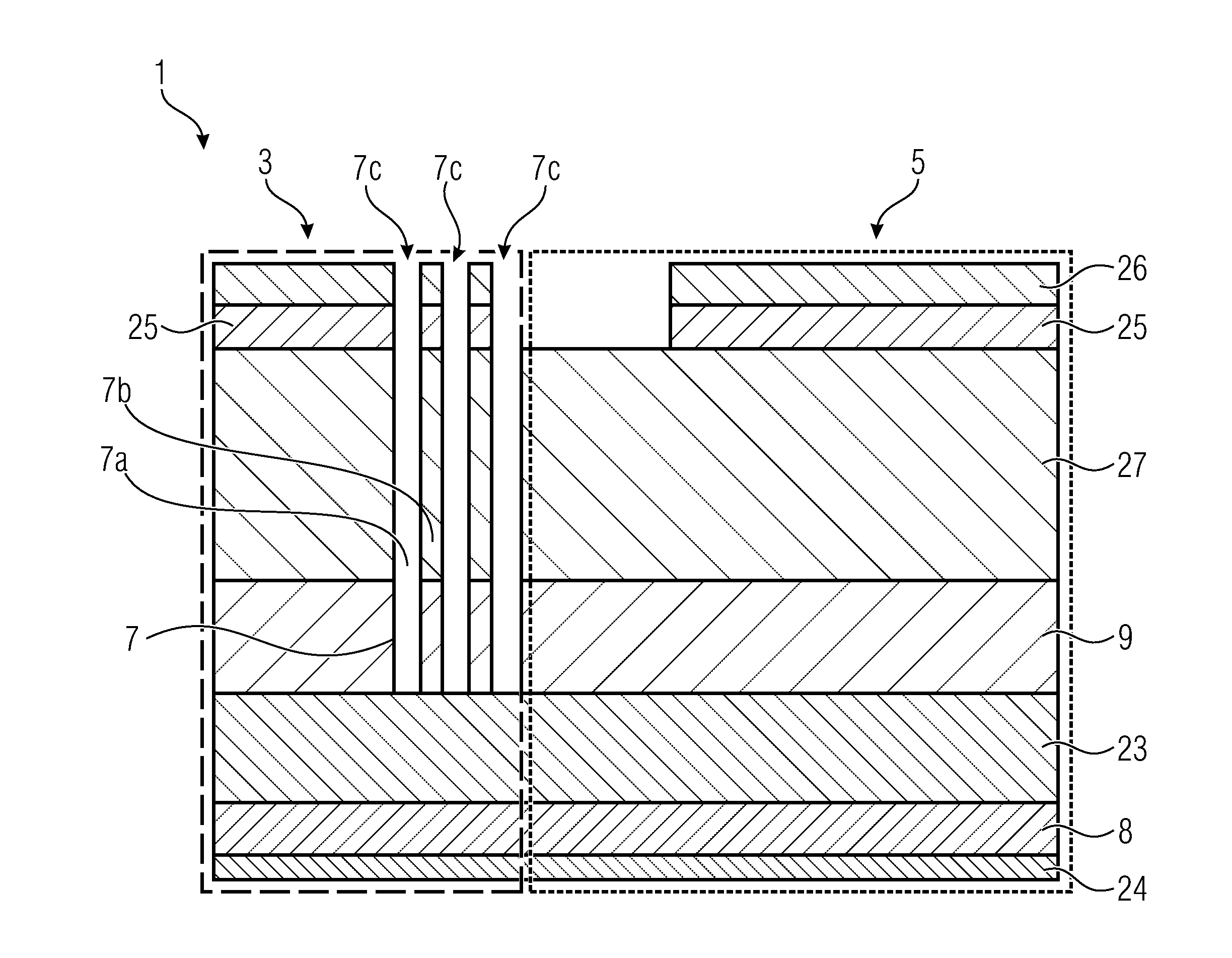
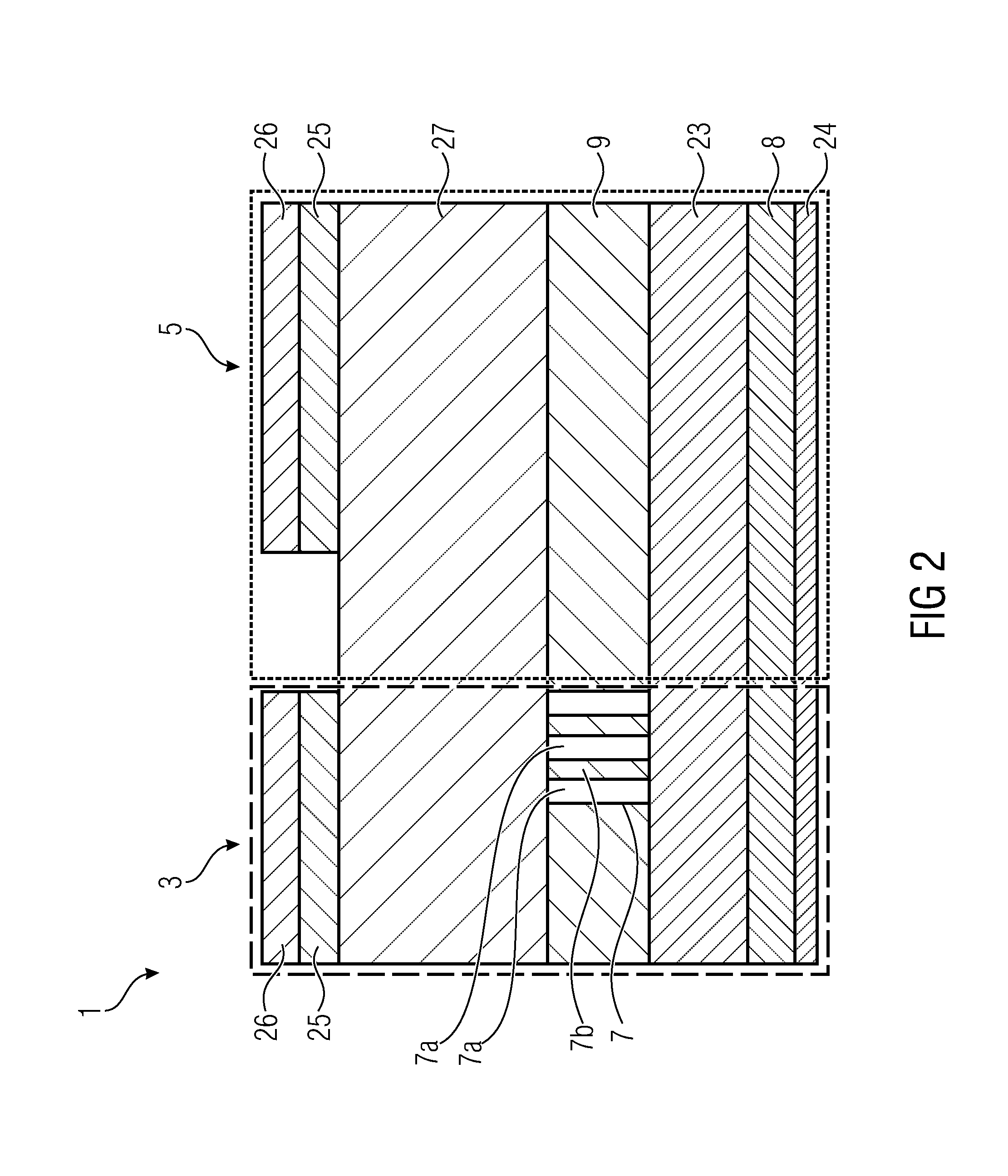
[0040]FIG. 2 shows a cross-sectional view of an exemplary combined Gain-SOA Chip 1 according to the present invention. The combined Gain-SOA Chip 1 comprises at least two different regions, wherein the gain section 3 is provided in...


PUM


Abstract

A combined Gain-SOA (Semiconductor Optical Amplifier) Chip is provided for forming a hybrid laser by a combination with an external reflector, the Gain-SOA Chip comprising a gain section and an SOA section, wherein an optical grating is arranged between the gain section and the SOA section.

Description

BACKGROUND OF THE INVENTION[0001]The present invention is concerned with a combined Gain-SOA (Semiconductor Optical Amplifier) chip for forming a hybrid laser, and a hybrid laser comprising the combined Gain-SOA Chip.[0002]Hybrid integrated tunable lasers with small line widths, which are increasingly used in optical systems, may comprise an optical output power that is too low for many applications. Such lasers consist of a passive tunable reflector for wavelength selection (e.g. made from silicon, polymer or glass) and an active gain chip (usually an InP chip). In order to increase the optical power, either a separate EDFA (Erbium Doped Fiber Amplifier) or a separate SOA (Semiconductor Optical Amplifier) is coupled downstream [1], which amplifier has to be coupled to the tunable laser in a complicated and precise manner in order to realize a lossless optical coupling.[0003]Conventional approaches, as discussed in [2], suggest integrating a semiconductor optical amplifier on the ga...

Claims


Application Information

Patent Timeline
IPC IPC(8): H01S5/12H01S5/10H01S5/125
CPCH01S5/101H01S5/125H01S5/0265H01S5/06256H01S5/50H01S5/1085H01S5/1228H01S5/141H01S5/06258
Inventor MÖHRLE, MARTIN
Owner FRAUNHOFER GESELLSCHAFT ZUR FOERDERUNG DER ANGEWANDTEN FORSCHUNG EV
Why Eureka
Try Eureka