
Method for manufacturing iron nuggets

a manufacturing method and technology for iron nuggets, applied in metal processing, furnace types, furnaces, etc., can solve the problems of significant expansion, decarburization and reduction of the amount of carbon in the iron nuggets, and degradation of the quality of the iron nuggets, so as to increase the feo amount in a slag, reduce the amount of sulfur contained in the iron nuggets, and improve the quality of the reduced iron

Inactive Publication Date: 2016-08-18
KOBE STEEL LTD
View PDF4 Cites 4 Cited by
  • Summary
  • Abstract
  • Description
  • Claims
  • Application Information

AI Technical Summary

Benefits of technology

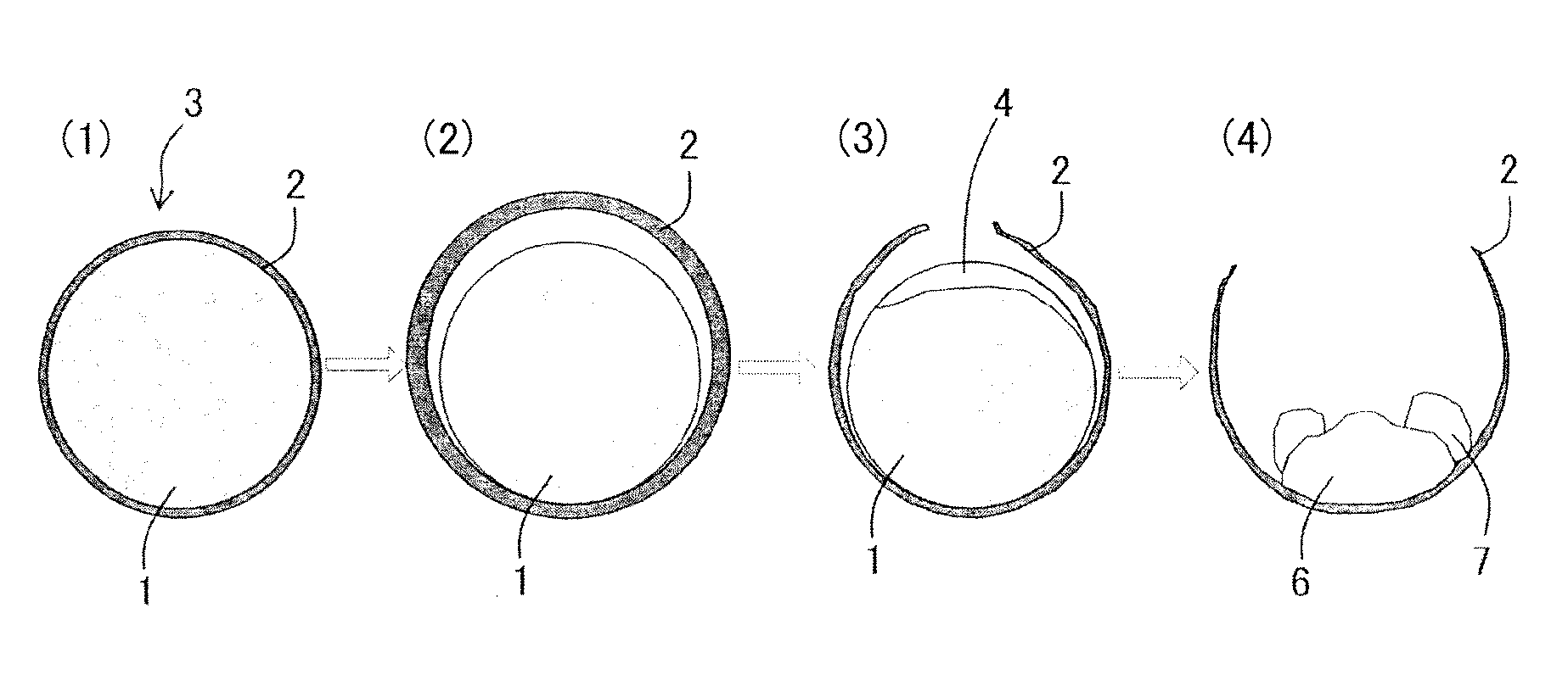
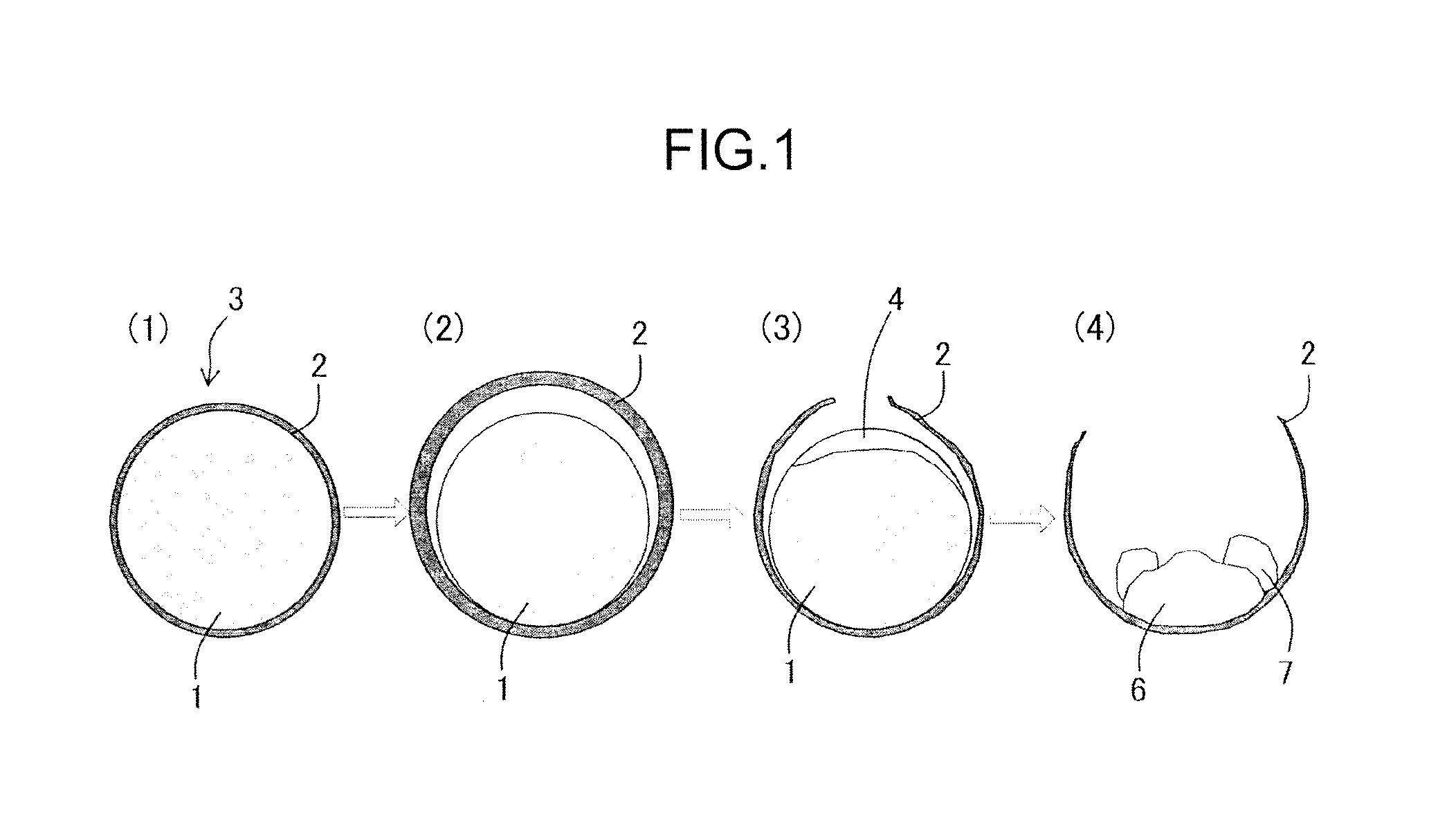
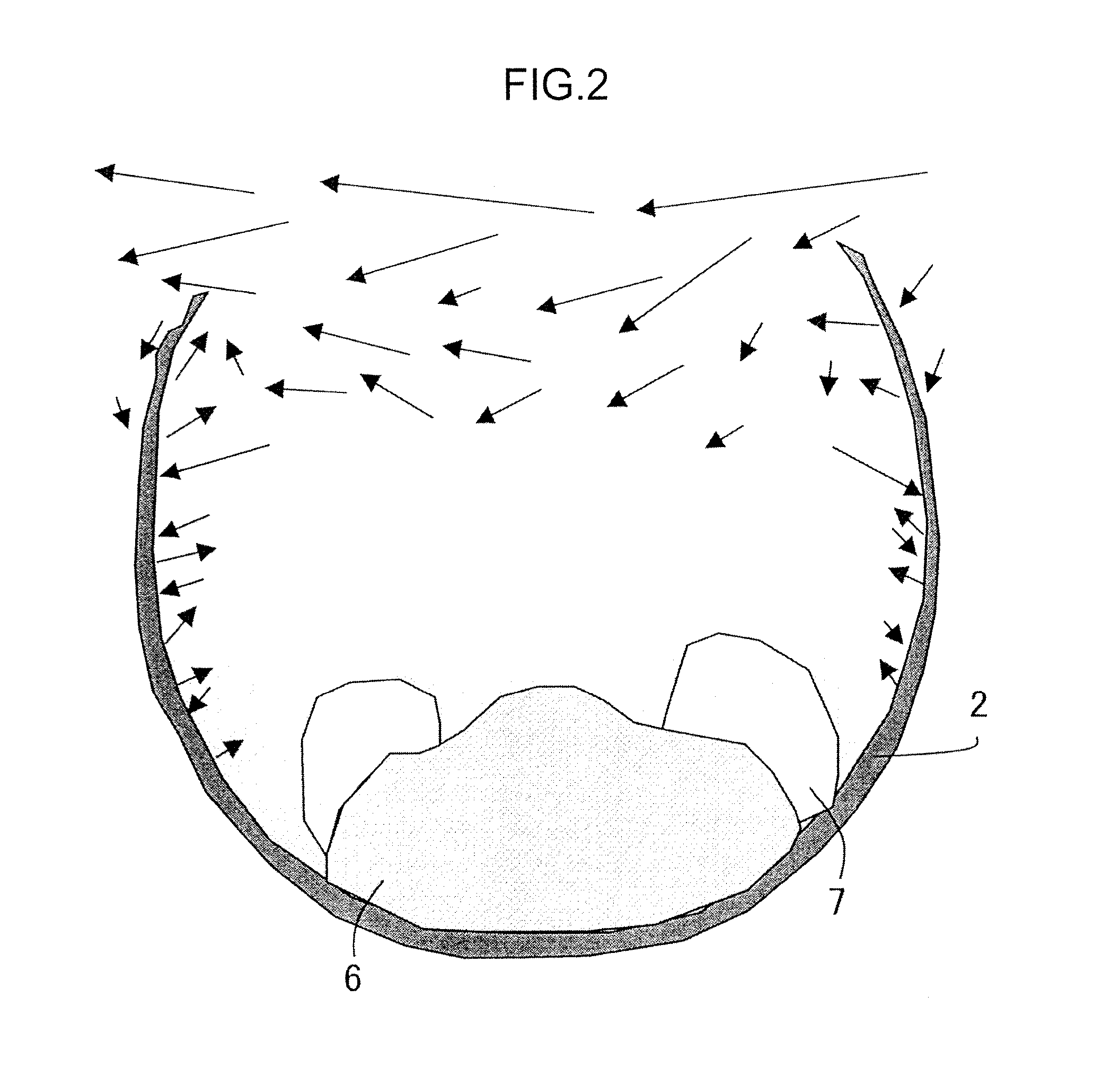
The present invention provides a method for manufacturing iron nuggets which prevents reoxidation and improves the quality of the reduced iron. The method involves heating and reducing agglomerates containing iron oxide, and using a coating layer formed from a fluid carbonaceous material to prevent oxidation while the agglomerates are heated. The coating layer acts as a windbreak wall, resulting in a decrease in FeO in the slag and an increase in the carbon content of the iron nuggets. This reduces the amount of sulfur and carbon dioxide in the production process, which improves the quality of the iron nuggets. Additionally, slag foaming is prevented, resulting in the formation of more uniform-sized iron nuggets and improved separation from slag.

Problems solved by technology

Where the amount of sulfur in the iron nuggets increases, the quality of the iron nuggets is degraded.
Further, FeO in the slag reacts with carbon [C] contained in the generated semi-molten iron and molten iron, thereby causing decarburization and reducing the amount of carbon in the iron nuggets.
Following the decarburization reaction, a large number of fine CO gas bubbles are present in the slag, thereby causing significant expansion.
The resultant problem is that heat supplied from the upper section of the heating furnace is shielded, the reaction time is greatly increased, and productivity is decreased.
Yet another problem is that where slag foaming is initiated, the iron nuggets assume an irregular shape, the iron nuggets are insufficiently separated from part of the slag, and iron nuggets quality is degraded.

Method used


Image

  • Method for manufacturing iron nuggets
  • Method for manufacturing iron nuggets
  • Method for manufacturing iron nuggets

Examples


experimental example 1

[0086]In the present experimental example, agglomerates having on the surface a coating layer including a fluid carbonaceous material and agglomerates having no coating layer were prepared, the agglomerates were heated in a heating furnace, and it was investigated whether or not the reoxidation of the obtained iron nuggets was suppressed.

[0087]Initially the agglomerates including iron oxide and a carbonaceous reducing agent were manufactured.

[0088]An iron ore of the composition presented in Table 1 below was used as the iron oxide. In Table 1, T. Fe means “total iron”. The iron ore to be used was ground such that the ore with a particle size of 44 μm or less constituted 67 mass %.

[0089]A carbonaceous material with the composition presented in Table 2 was used as the carbonaceous reducing material. In Table 2, T. C means “total carbon” and F. C means “fixed carbon”. The carbonaceous material to be used was ground such that the coal with a particle size of 75 μm or less constituted ab...

experimental example 2

[0108]In the present experimental example, the agglomerates were manufactured by changing the thickness of the coating layer formed on the surface of core portions, the produced agglomerates were heated in a heating furnace, and it was investigated whether or not the reoxidation of the obtained iron nuggets was suppressed.

[0109]Initially, green pellets in which the coating layer was formed on the surface of core portions were manufactured according to the procedure of Experimental Example 1 by changing the thickness of the coating portion. The core portions on which the coating layer was formed were cut and the thickness of the coating layer was checked by observing the cross section under an optical microscope. As a result, the average thickness of the coating layer was 0.30 mm to 2.00 mm.

[0110]The green pellets obtained by forming the coating layer on the surface of the core portions were charged into a drier and heated for about 1.0 h at 160° C. to 180° C. to remove the adhered w...

experimental example 3

[0124]In the present experimental example, the agglomerates were manufactured by using a non-fluid carbonaceous material for including in the coating layer to be formed on the surface of the core portions, the agglomerates were heated in the heating furnace, and it was examined whether or not the reoxidation of the obtained iron nuggets was suppressed.

[0125]Initially, green pellets in which the coating layer with an average thickness of 0.50 mm was formed on the surface of the core portions were manufactured according to the procedure of Experimental Example 1. In this case, anthracite was used as a non-fluid carbonaceous material instead of the fluid bituminous coal. The composition of the anthracite is presented in Table 6 below.

[0126]The green pellets obtained by forming the coating layer on the surface were charged into a drier and heated for about 1.0 h at 160° C. to 180° C. to remove the adhered water, thereby producing spherical dry pellets (i.e., agglomerates).

[0127]Then, th...


PUM

PropertyMeasurementUnit
thicknessaaaaaaaaaa
mass %aaaaaaaaaa
temperatureaaaaaaaaaa

Abstract

Provided is a method for manufacturing iron nuggets by which reduced iron obtained by heating and reducing agglomerates, or iron nuggets obtained by melting and aggregating the reduced iron can be prevented from reoxidation inside a movable hearth heating furnace and quality of the reduced iron can be improved. The method involves charging and heating agglomerates including iron oxide and a carbonaceous reducing agent on a hearth of a movable hearth heating furnace, reducing and melting the iron oxide in the agglomerates, and then discharging obtained iron nuggets to the outside of the furnace and recovering the iron nuggets. The agglomerates have a coating layer, including a fluid carbonaceous material, on the surface.

Description

TECHNICAL FIELD[0001]The present invention relates to a method for manufacturing iron nuggets by heating agglomerates including iron oxide, for example, iron ore, and a carbon-containing reducing agent (also referred to hereinbelow as “carbonaceous reducing agent”) and reducing and melting the iron oxide contained in the agglomerates.BACKGROUND ART[0002]For example, the technique disclosed in Patent Literature 1 is known as a method for manufacturing iron nuggets by heating agglomerates including iron oxide and a carbonaceous reducing agent. This literature indicates that in a method for manufacturing a solid metal product from carbon including a metal-bearing compound, the surface of a molded product including carbon and the metal-bearing compound is coated with a treatment substance and the covered molded product is supplied on a furnace hearth and heated. It is also indicated that the coating layer includes a carbonaceous compound.CITATION LISTPatent Literature[0003]Patent Docume...

Claims


Application Information

Patent Timeline
Patent Type & Authority Applications(United States)
IPC IPC(8): C21B13/10C22B1/24C22B1/245C21B11/08C21B13/00
CPCC21B11/08C22B1/24C22B1/245C21B13/0046C22B1/2406C21B13/105Y02P10/136C21B2300/02C21B13/0066B22F2998/10Y02P10/134C22C33/0235B22F2201/04
Inventor ITO, SHUZOHATAKEYAMA, TAIJIO, SHORINSUGITATSU, HIROSHI
Owner KOBE STEEL LTD
Learn More