Anode-free rechargeable battery
a rechargeable battery, anode-free technology, applied in the direction of electrochemical generators, cell components, transportation and packaging, etc., can solve the problems of low ce, high reactivity, and the inability to commercialize rechargeable batteries based on li metal anodes in large scal
- Summary
- Abstract
- Description
- Claims
- Application Information
AI Technical Summary
Benefits of technology
Problems solved by technology
Method used
Image

Examples
example 1
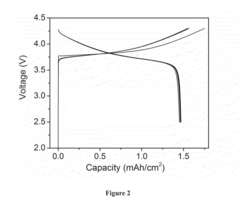
[0044]A coin cell type anode-free Li rechargeable battery was assembled using copper (Cu) foil as the anode current collector, a LiNi1 / 3Co1 / 3Mn1 / 3O2 (NMC) thick film coated on an Al substrate as the cathode, Celgard™ 2045 as the separator, and 4 M LiFSI in DME as the liquid electrolyte. The Cu foil substrate was washed by immersing it in 1 M hydrochloric acid for 10 min, and rinsed by distilled water and acetone three times, respectively, followed by a quick drying in a vacuum chamber. The NMC electrode was provided by Argonne National Laboratory with a nominal capacity of ˜1.5 mAh / cm2. The cell was cycled between 2.5 and 4.2 V at a constant current density of 0.5 mA / cm2. FIG. 2 shows the charge-discharge profiles of the Cu|NMC type battery. This cell delivers an initial charge / discharge capacity of 1.75 / 1.47 mAh / cm2, giving a high initial Coulombic Efficiency of 84%. The reversible capacity is identical to its nominal capacity and keeps stable without distinct capacity degradation ...
example 2
[0045]A coin cell type anode-free Li rechargeable battery was assembled using copper foil as the anode current collector, LiFePO4 film as the cathode, Celgard™ 2045 as the separator, and 4 M LiFSI in DME as the liquid electrolyte. A LiFePO4 cathode is a free standing film (no substrate) composed of LiFePO4, conductive carbon (Super P™) and Polytetrafluoroethylene (PTFE) binder in a ratio of 70:20:10. The cell was cycled between 3 and 3.8 V at a current density of 0.2 mA / cm2. FIG. 3 shows the voltage as a function of capacity of the cells during 100 cycles. The cell exhibits an initial discharge capacity of 2.2 mAh / cm2. FIG. 4 shows the Coulombic efficiency of this Cu|LiFePO4 battery as a function of cycle number. The average Coulombic Efficiency of the cell was 99.1% over 100 cycles (excluding the first cycles which exhibit relatively large capacity loss of 9.5%).
example 3
[0046]A sample with a structure similar to the one described in Example 2 was cycled at a low current rate of 0.2 mA / cm2 for the first four cycles then cycled at 0.5 mA / cm2 for further cycles. A coin cell type anode-free Li rechargeable battery was assembled using copper foil as the anode current collector, a free standing LiFePO4 film (LiFePO4:Super P™:PTFE=70:20:10) as the cathode, Celgard™ 2045 as the separator, and 4 M LiFSI in DME as the liquid electrolyte. The cell was initially cycled between 3 and 3.8 V at a current density of 0.2 mA / cm2 for the first 4 cycles, then cycled at a current density of 0.5 mA / cm2. FIG. 5 shows the voltage profiles of the battery as a function of capacity in the first five cycles. The cell exhibits an initial discharge capacity of 1.8 mAh / cm2. FIG. 6 shows the Coulombic efficiency of a Cu|LiFePO4 battery as a functional of cycle number. The initial Coulombic efficiency of the cell is more than 92%. The average Coulombic efficiency of the cell is ˜9...
PUM
| Property | Measurement | Unit |
|---|---|---|
| Coulombic Efficiency | aaaaa | aaaaa |
| Coulombic efficiency | aaaaa | aaaaa |
| current density | aaaaa | aaaaa |
Abstract
Description
Claims
Application Information