Oil recovery processes at high salinity carbonate reservoirs

a high salinity carbonate and oil recovery technology, applied in the direction of sustainable manufacturing/processing, fluid removal, borehole/well accessories, etc., can solve the problems of low oil mobility, inability to use these materials as surfactants, and cost-effective addition, etc., to reduce the viscosity

Inactive Publication Date: 2016-10-06
KING FAHD UNIVERSITY OF PETROLEUM AND MINERALS
View PDF2 Cites 22 Cited by
  • Summary
  • Abstract
  • Description
  • Claims
  • Application Information

AI Technical Summary

Benefits of technology

[0013]In one aspect of the present invention, there is provided a process for recovering hydrocarbon from a carbonate reservoir. The process comprises injecting the carbonate reservoir with a first solution to recover a first amount of hydrocarbon and injecting the carbonate reservoir with a second solution and a third solution to recover a second amount of hydrocarbon. The second solution comprises an amphoteric fluorosurfactant and the third solution comprises supercritical CO2. The injecting with the second solution and the third solution displaces the second amount of hydrocarbon from the carbonate reservoir by pushing the second amount of hydrocarbon and reducing the viscosity of the second amount of hydrocarbon.

Problems solved by technology

The residual oil is usually heavy: having high viscosity and therefore resulting in low oil mobility.
However, as CO2 is highly mobile, this technique encounters problems of viscous fingering, reservoir heterogeneity and gravity overriding or segregation, as the ability to control the mobility of CO2 is limited (S. I. Bakhtiyarov, A. K. Shakhverdiev, 2007, “Effect of Surfactant on Volume and Pressure of Generated CO2 Gas”, SPE 106902; B. Bai, R. B. Grigg, Y. Liu and Z. Zeng, 2005, “Adsorption Kinetics of Surfactant Used in CO2-Foam Flooding Onto Berea Sandstone”, SPE 95920; R. B. Grigg, B. Bai, 2005, “Sorption of Surfactant Used in CO2 Flooding onto Five Minerals and Three Porous Media”, SPE 93100; John D. Rogers, Reid B. Grigg, October 2001, “A Literature Analysis of the WAG Injectivity Abnormalities in the CO2 Process”, SPE Reservoir Evaluation & Engineering, 375-386—each incorporated herein by reference in its entirety).
The identification of cost-effective, environmentally friendly materials that dissolve in supercritical CO2 for use in EOR has also posed a great challenge.
Supercritical CO2-philes (materials soluble in supercritical CO2) are rare and use of these materials as surfactants was not possible due to the high pressures required to dissolve them (a result of their high molecular weight) and the inability to cost-effectively add a hydrophilic group for solubility in the bulk recovery fluid (water).
Most of the efforts attempted hitherto are plagued with deficiencies that restrict their applicability.
The inability of foam generation or instability of the generated foam means that the problem of CO2 high mobility has not been successfully tackled.
Adsorption of the surfactant on the rock material is another factor which reduces the effectiveness of the foam system.
Moreover, the number of foam experiments that have been conducted carbonate rocks is very limited; those conducted on long cores are even fewer.

Method used


Image

  • Oil recovery processes at high salinity carbonate reservoirs
  • Oil recovery processes at high salinity carbonate reservoirs
  • Oil recovery processes at high salinity carbonate reservoirs

Examples


example 1

Materials

Core Samples

[0095]Indiana Limestone cores of 12″ length and 1.5″ diameter were used in all the experiments. The core samples were procured form Kocurek Industries (USA). The supplier specified porosity and permeability values were 19% and 70 and respectively.

Salts

[0096]Five different salts were needed to prepare both the synthetic formation and injection brines. These salts were Sodium Chloride (NaCl), Sodium Hydroxide (NaOH), Sodium carbonate (Na2CO3), Calcium Chloride (CaCl2) and Magnesium Chloride (MgCl2).

Brines

[0097]Two types of brines were required for the experiments: Formation brine to saturate the core initially and injection brine for water-flooding. The concentrations of the brines resemble Saudi reservoir connate water and sea water for saturation and injection respectively. The brines were stirred and heated for 48 hours prior to usage in the experiments. Table 1 shows the concentration of the two brine solutions. TDS indicates the total dissolved solids (TDS) o...

example 2

Equipment

Core-flooding Experimental Setup

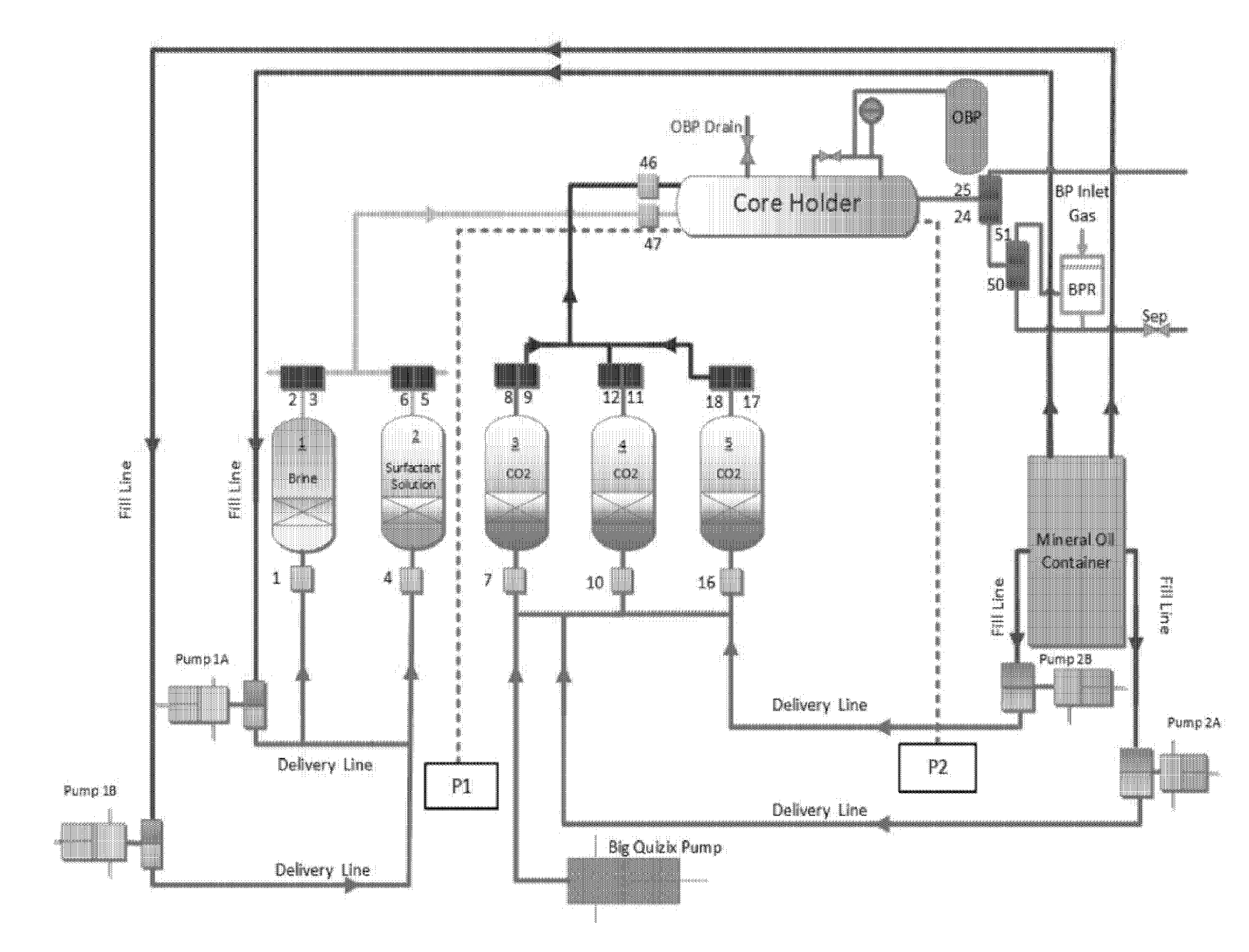
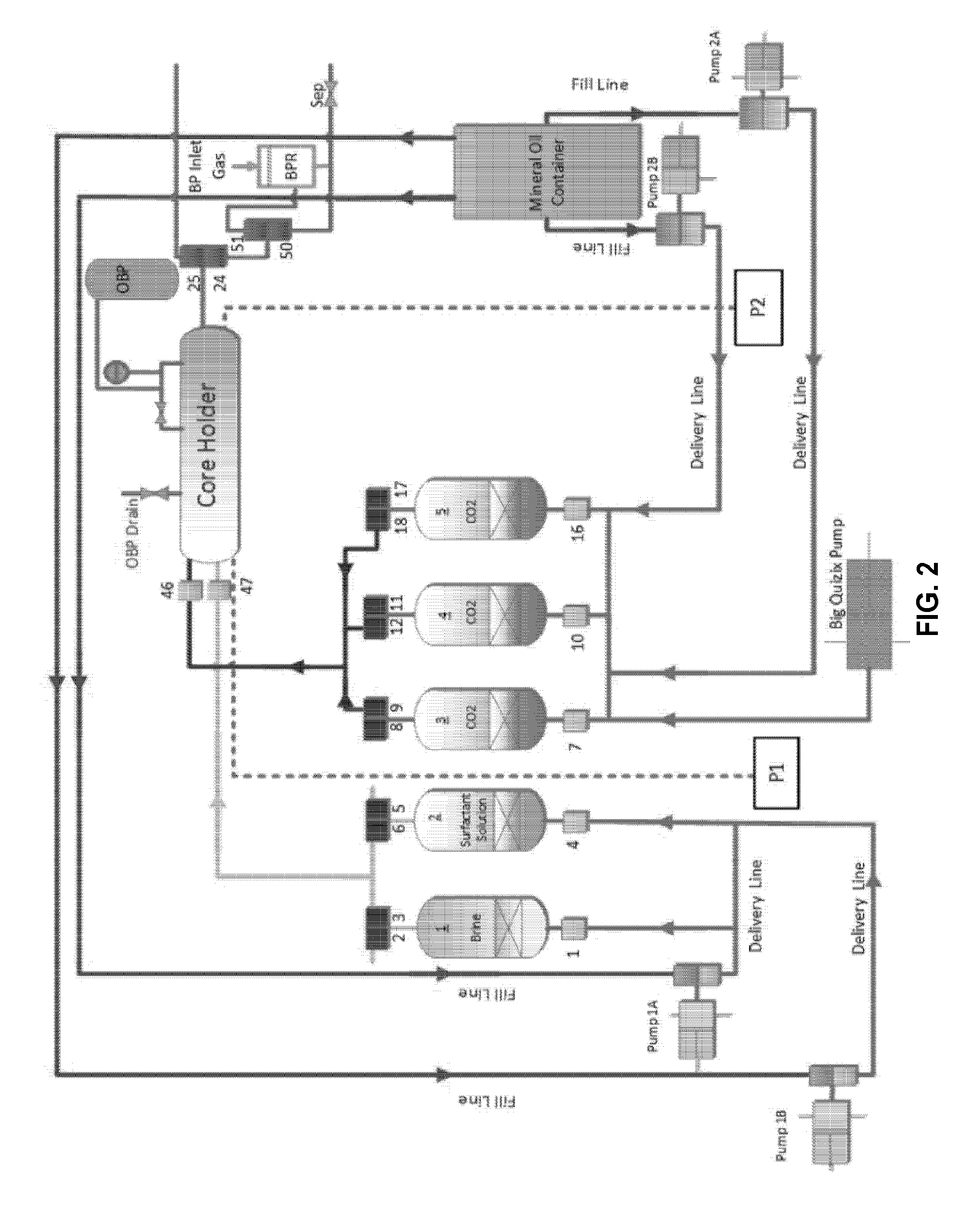
[0102]The core-flooding system used herein is basically a reservoir condition condensate depletion system that was modified to suit the required specifications. The schematic of the core-flooding experimental system is shown in FIG. 2. The system includes an oven, five floating piston fluid cylinders of various volumes, Quizix pumping system, back pressure regulator and the core holder. The components of the flow, control and measurement systems are installed on the ends of the oven, on its roof, as well as within the oven itself. The system includes 72 air operated solenoid valves that are controlled by a software program on a dedicated computer. The flow control system components are all inside the oven. All the pressure transducers and Quizix pump controllers are external to the oven. The system is hooked up to an automatic data logging system which works with the software to record all the data during the experiments in a Microsoft Excel ...

example 3

Experimental Plan

[0114]A number of experiments were planned in which the parameters were varied to accommodate the effect of various factors on the increase in oil recovery. Three injection strategies were considered:[0115]1. CO2 Flooding—Base case.[0116]2. Alternate Surfactant and CO2 Flooding—Slugs of different ratios of surfactant solution and CO2 were injected alternatively in subsequent experiments.[0117]3. Continuous Surfactant and CO2 Flooding—Surfactant solution and CO2 was injected simultaneously.

[0118]The experiments were designed to depict reservoir conditions, thus some of the parameters were kept constant. These include:[0119]Temperature: 90° C.[0120]Pressure: 2500 psi (overburden pressure) or 1800 psi (backpressure)[0121]Crude Oil: Uthmaniya dead oil (30.1° API)[0122]Core: Indiana Limestone 12″×1.5″.[0123]Brine Salinity: Connate Water=213,734 TDS; Injection Brine=57,670 TDS[0124]Oil Soak Period: 5 days (aging time)[0125]Injection Flow Rates: Oil=0.25 cc / min; Water=0.5 ...


PUM

PropertyMeasurementUnit
volume ratioaaaaaaaaaa
temperatureaaaaaaaaaa
critical pressureaaaaaaaaaa

Abstract

A process for recovering oil from a carbonate reservoir of high salinity, wherein supercritical CO2 floodings are combined with a fluorosurfactant in the tertiary recovery. Embodiments include alternating injection and co-injection schemes of the supercritical CO2 and the fluorosurfactant. A stable fluorosurfactant-CO2 foam that is not susceptible to the harsh conditions of the reservoir (temperature, pressure and salinity) can be successfully generated, leading to a reduction in the mobility of CO2, an increase in the mobility of the reservoir oil, higher contact between the injected fluid with the oil and a better sweep efficiency of the oil.

Description

BACKGROUND OF THE INVENTION[0001]1. Technical Field[0002]The present invention relates to processes and techniques for oil recovery. More specifically, combined supercritical CO2 and surfactant solution injection strategies are deployed in these processes to effectively displace oil from reservoirs of high salinity.[0003]2. Description of the Related Art[0004]The “background” description provided herein is for the purpose of generally presenting the context of the disclosure. Work of the presently named inventors, to the extent it is described in this background section, as well as aspects of the description which may not otherwise qualify as prior art at the time of filing, are neither expressly or impliedly admitted as prior art against the present invention.[0005]Crude oil development and production in global oil reservoirs can include up to three distinct phases: primary, secondary and tertiary (or enhanced) recovery. During primary recovery, reservoir drive comes from a number ...

Claims


Application Information

Patent Timeline
Patent Type & Authority Applications(United States)
IPC IPC(8): C09K8/584E21B43/16C09K8/594E21B43/20
CPCC09K8/584C09K8/594E21B43/164E21B43/20E21B43/24Y02P90/70
Inventor JANGDA, ZAID ZAFFARSULTAN, ABDULLAH S.
Owner KING FAHD UNIVERSITY OF PETROLEUM AND MINERALS
Why Eureka
Try Eureka