Low-cost fiber optic sensor for large strains

a fiber optic sensor, low-cost technology, applied in the direction of glass optical fibre, clad optical fibre, instruments, etc., can solve the problems of large strain magnitude, complicated and expensive, limited strain that can be used for making measurements, etc., to achieve high elastic and extensible

Inactive Publication Date: 2016-10-20
WASHINGTON STATE UNIVERSITY
View PDF32 Cites 9 Cited by
  • Summary
  • Abstract
  • Description
  • Claims
  • Application Information

AI Technical Summary

Benefits of technology

[0006]It is therefore an object of the present invention to provide a highly elastic and extensible fiber optic material.
[0007]It is another object of the invention to provide a long period grating fiber optic sensor structure that can be made arbitrarily large at low cost but which remains physically robust and of comparable accuracy to much smaller currently typical fiber optic sensors.
[0008]It is a further object of the invention to provide a long period grating fiber optic sensor which can measure strains as large as 200% of unstressed sensor length.

Problems solved by technology

However, at the present state of the art, the amount of strain that can be used for making measurement is limited by the nature of the materials which can perform as fiber optic cables and sensors.
Specifically, the glass or hard plastic materials that have been traditionally used have a large value of their Young's modulus of elasticity (hereinafter sometimes simply “modulus”) and very short elongation before fracturing which complicates making measurements involving large magnitudes of strain.
Moreover, known methods of making sensors such as Bragg gratings, which are well known and understood and used for optical notch filters, optical multiplexers and demultiplexers or optical add-drop multiplexers, are complicated and expensive as well as resulting in sensors which are better adapted to relatively small strain dimensions.
Longer period FBGs have a grating periodicity in the range of 100 microns to 1 millimeter and are fabricated by ultraviolet (UV) radiation, ion implantation, femtosecond infrared (IR) radiation, carbon dioxide laser irradiation or diffusion of dopants into the core of a fiber optic cable which are expensive and complex with often relatively small process parameter windows.
These factors generally limit usable strain ranges to 5% or less of the sensor dimensions while large strain measurements are a critical problem for many applications such as monitoring the structures of aircraft, ships, buildings and other large structures and constructions that are subject to aging, positional shifting, or deformation by applied forces or other conditions of environment and / or use as well as for monitoring any other aspects of structural health.
Moreover, the parameters of interest in such measurements may favor measurement over a substantial continuous distance such as for measurement of settling or subsidence or dimensional creep of materials under substantial force for an extended period of time which may require large sensor physical size whereas typical fiber optic sensors are very small and their cost of manufacture is generally proportional to their length.
Therefore, fiber optical measurement over significant distances has been limited to measurement of distances between sensors (e.g. forming a Fabry-Perot cavity therebetween); requiring a costly and complicated arrangement that, in turn, requires optical measurements of extremely high precision, such as reflection return time or interference pattern detection and analysis rather than much simpler techniques of measurement of light intensity or spectrum.

Method used


Image

  • Low-cost fiber optic sensor for large strains
  • Low-cost fiber optic sensor for large strains
  • Low-cost fiber optic sensor for large strains

Examples


Embodiment Construction

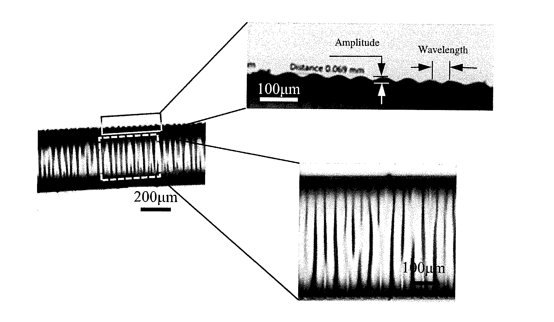
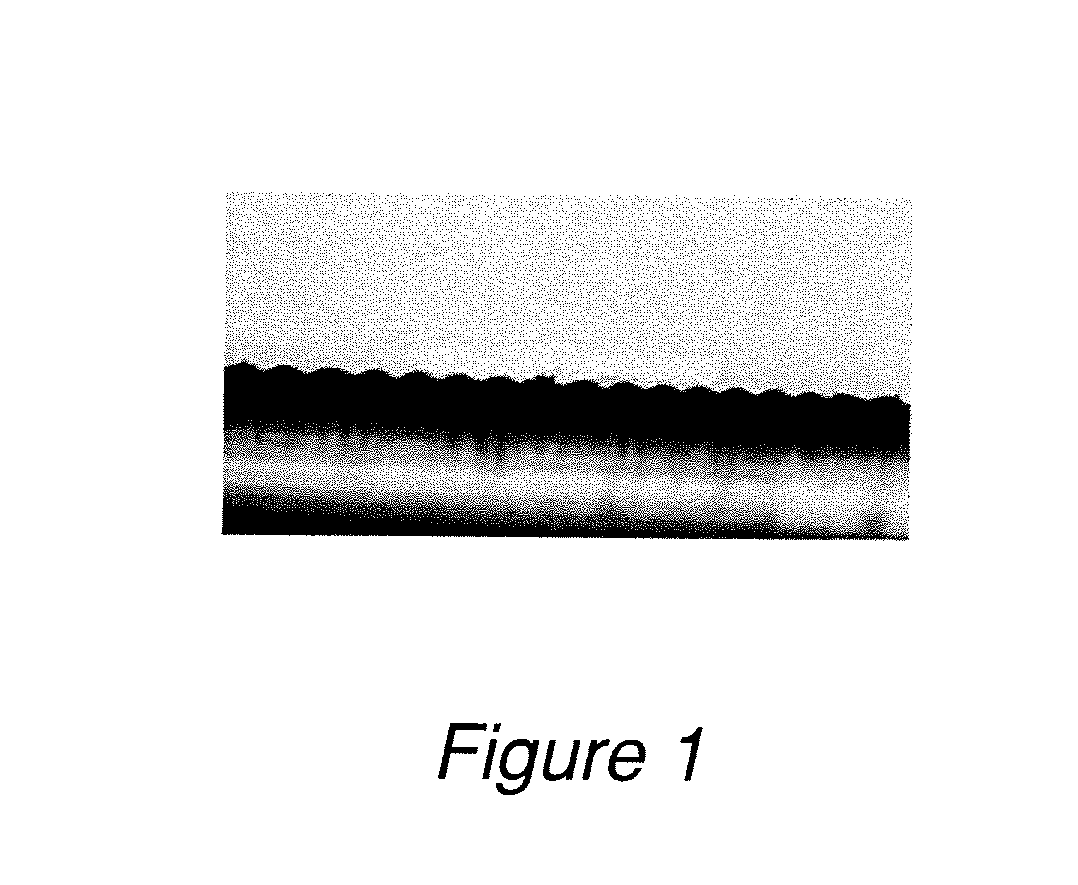
[0025]Referring now to the drawings, and more particularly to FIG. 1, there is shown a portion of a lateral cross-section of a representative length of fiber optic sensor in accordance with the invention. In the portion of the lateral cross-section shown, a portion of a fiber optic core, preferably of polydimethylsiloxane (PDMS), is encased in a hard shell or overlayer (e.g., referred to as a skin or cladding; skin tending to infer a small thickness and cladding inferring a greater thickness approaching one half the unstressed diameter of the core which is considered at the present time to be a practical limit on cladding thickness but is not critical to the useful practice of the invention) that may comprise any of a plurality of materials as will be described below with an undulating surface at the interface of the two materials with the undulations being substantially uniform in both height and period along the fiber length. Since a small amount of manufacturing variability inevi...


PUM

PropertyMeasurementUnit
thicknessaaaaaaaaaa
elongationaaaaaaaaaa
wavelengthaaaaaaaaaa

Abstract

A fiber grating device of low cost and arbitrary length is formed on a portion of a portion or the entirety of a highly elastic fiber optic core having a low Young's modulus of elasticity by causing elongation of the fiber optic core and forming or depositing a hard skin or cladding on the elongated fiber optic core. When the stress is then released, the hard skin or cladding buckles (including elastic or plastic deformation or both) to form wrinkles at the interface of the fiber optic core and the hard skin or cladding which are oriented circumferentially and highly uniform in height and spacing which can be varied at will by choice of materials, stretching, and thickness and composition of the cladding. Since the elastic elongation of the fiber optic core portion may be 200% or greater, an unprecedented measurement range is provided.

Description

CROSS-REFERENCE TO RELATED APPLICATIONS[0001]This application claims benefit of priority of U.S. Provisional Application 62 / 147,495, filed Apr. 14, 2015, which is hereby incorporated by reference in its entirety.FIELD OF THE INVENTION[0002]The present invention generally relates to fiber optic sensors for measurement of physical parameters and, more particularly, to fiber optic sensors for measurement of physical parameters which involve large levels of strain or large dimensions.BACKGROUND OF THE INVENTION[0003]Fiber optic sensors have been used for a number of years to make measurements of physical parameters such as pressure, tensile or compressive forces, temperature, flow rate, humidity, refractive index and the like, particularly in hostile environments and long-duration monitoring since the optical properties and behaviors of fiber optic cables and sensors such as Bragg gratings are well-known, the technology of the optics is mature and the optical cables and sensors are part...

Claims


Application Information

Patent Timeline
Patent Type & Authority Applications(United States)
IPC IPC(8): G01B11/16G02B6/02
CPCG01B11/165G02B6/021G02B6/02142G02B6/02152G02B6/02395G01B11/18G02B6/02066G02B6/02071G02B6/02095G02B5/1847G02B2006/02161G02B6/0229G02B6/02123
Inventor PANAT, RAHULLI, LEI
Owner WASHINGTON STATE UNIVERSITY
Why Eureka
Try Eureka