Magnetic structures for low leakage inductance and very high efficiency

a magnetic structure and leakage inductance technology, applied in the field of mechanical construction, can solve the problems of limited copper thickness, inability to offer a significant reduction of the total footprint to allow a reduction of the stray inductance, etc., to achieve the effect of improving the magnetic core configuration and winding arrangement, reducing the leakage inductance, and improving the utilization of copper

Inactive Publication Date: 2016-10-20
ROMPOWER TECH HLDG LLC
View PDF10 Cites 9 Cited by
  • Summary
  • Abstract
  • Description
  • Claims
  • Application Information

AI Technical Summary

Benefits of technology

[0006]The magnetic structures described in this invention provide an improved magnetic core configuration and winding arrangement. The magnetic structures described in this invention do offer a much lower leakage inductance, a better utilization of the copper a smaller footprint and in some implementations are very suitable for air core magnetics for very high frequency operation. The embodiments of this invention can be used for transformer application or inductive elements.
[0010]In one of the embodiments of this invention, which is described in FIG. 3A, and FIG. 3B there is a better copper optimization in the center tap topology. In center tap topology the secondary winding is not utilized properly. During one polarity the current flow through one of the secondary winding while, the other part of the secondary is not conducting. In one of the embodiments of this invention, the current in the secondary winding of the transformer circulates in both polarity in the center tap topology leading to a better copper utilization and lower power dissipation. Only a portion of the secondary winding is used for unidirectional current flow. The flooding with the copper over the primary winding will allow current flow freely to cancel the magnetic field of the primary winding to reduce the leakage inductance. Such implementation is presented in FIG. 6A,6B,6C,6D. In these figures, the copper surrounds the area penetration of the magnetic core. The current flows through the copper around the cores in order to cancel the magnetic field produced by the primary winding. Such a magnetic configuration using a U shape core, and using the copper structures as presented in the drawing have a very low leakage inductance.
[0011]In key one embodiment is depicted in FIG. 5A, FIG. 5B and FIG. 5C. This magnetic structure has four posts, which penetrates through the multilayer structure wherein the windings are embedded. This structure is the result of merging four E type magnetic cores, and in the process, a good portion of the magnetic core material is eliminated. That reduces the total footprint of the magnetic structure and reduces to total core loss, which is proportional with the volume of the core material. In this process the secondary winding merge as well as depicted in FIG. 5B. Each equivalent E shaped core is presented in FIG. 5C. Though the magnetic core with four legs are depicted in other prior art, the copper structures and the placement of the rectifier means changes the mode of operation and the performances.
[0012]In another embodiment depicted in FIG. 9A and 9B is presented the same four-legged magnetic structure wherein the output current flows out of the four openings and under the magnetic rectangular plate with a cutout in the middle to accommodate the four-legged transformer, which represents the output inductor. By placing the output connectors as depicted, the current is split and the magnetic core of the output choke does not have to penetrate the multilayer structure. In this way, we increase the utilization of the copper and decrease the total footprint of the transformer and output choke. This embodiment is very suitable for high output current applications.

Problems solved by technology

In such applications, the copper thickness is limited.
The prior art magnetic structures depicted in FIG. 1 can provide some reduction of the leakage inductance but they cannot offer a significant reduction of the total footprint to allow a reduction of the stray inductance.
Function of the winding configuration such a structure can benefit of a lower leakage inductance but it does not address the parasitic inductance, which is caused by the interconnection from the transformer to the power semiconductor devices.

Method used


Image

  • Magnetic structures for low leakage inductance and very high efficiency
  • Magnetic structures for low leakage inductance and very high efficiency
  • Magnetic structures for low leakage inductance and very high efficiency

Examples


Embodiment Construction

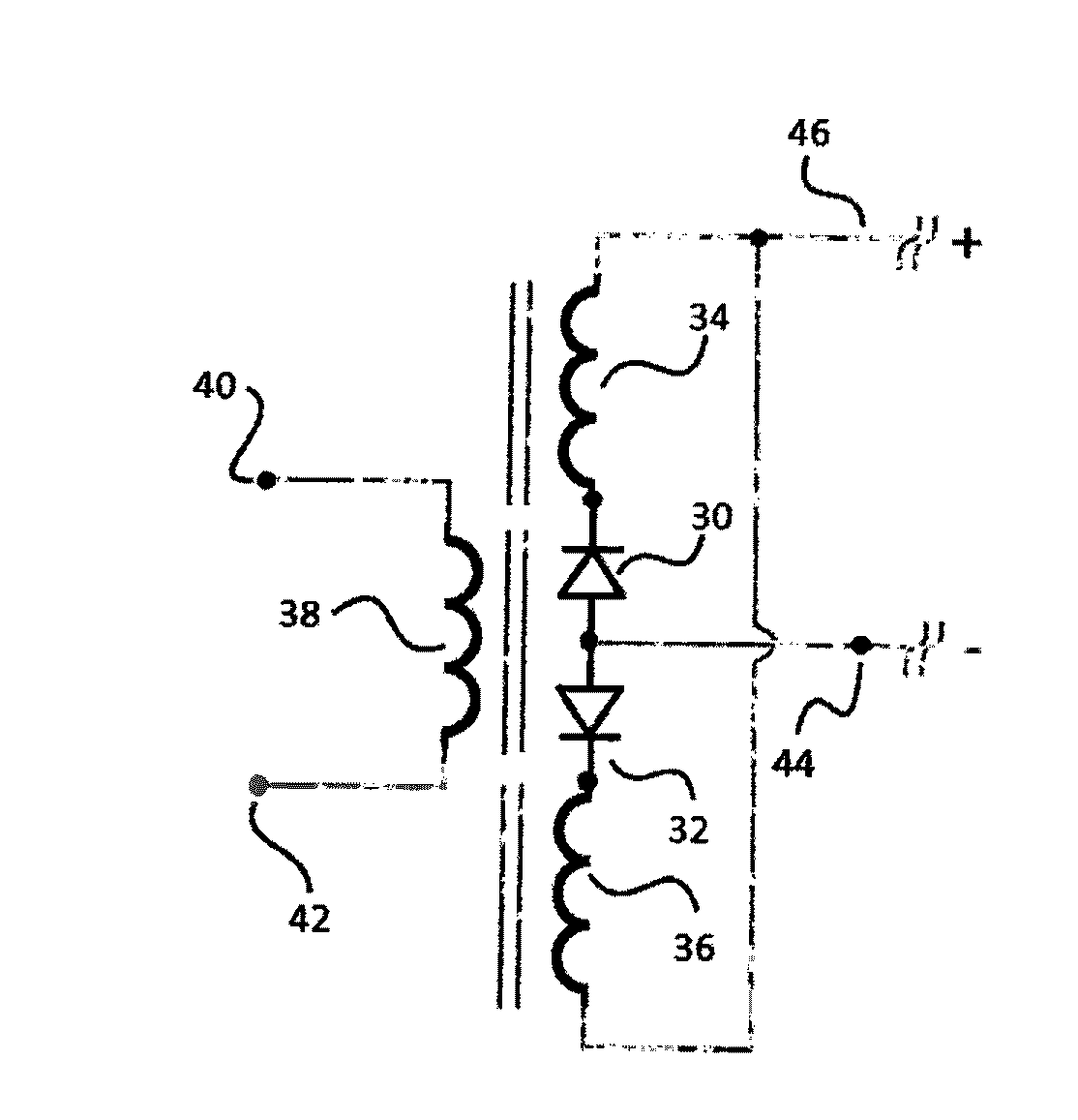
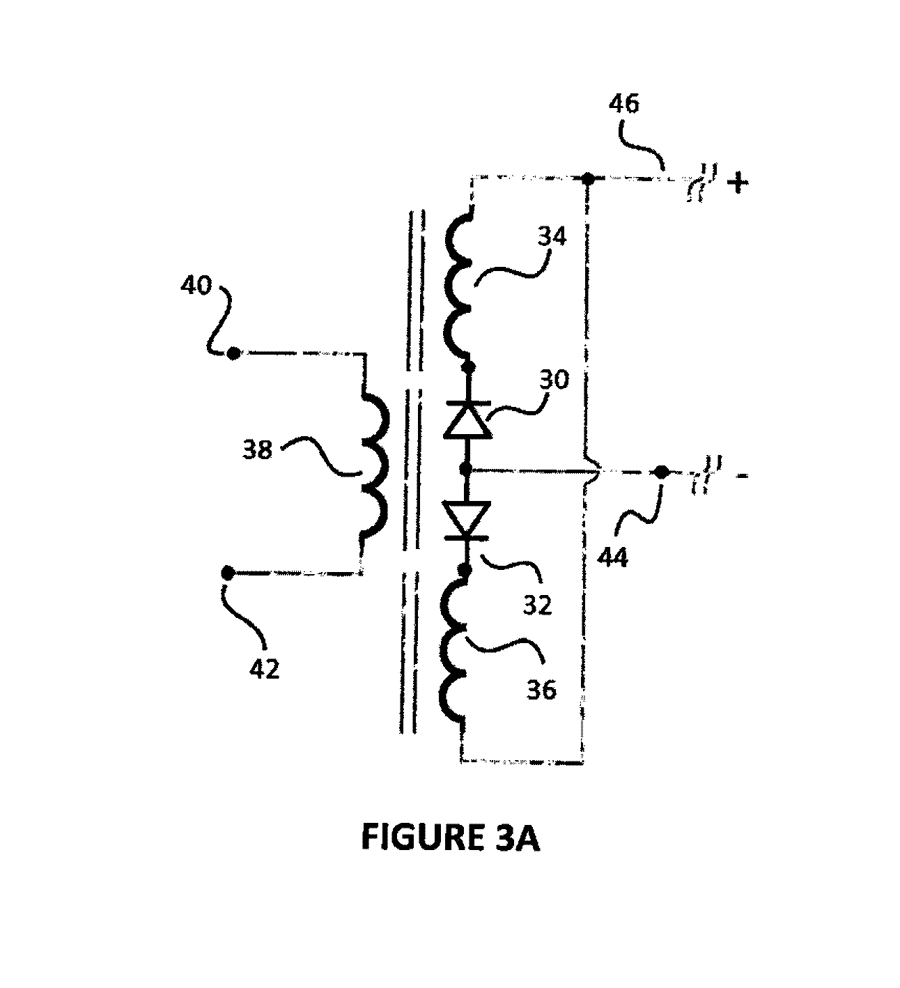
[0039]Presented in FIG. 3A is presented a center tap transformer structure having a primary winding 38, and two identical secondary windings 34 and 36. In the secondary side, there are two rectifier means, 30 and 32. The secondary rectifier means can be schottky diodes, synchronous rectifier using silicon power mosfets, GANs or other technologies. There is a positive output 46, and a negative output 44. Typically, the negative output it might be connected to the output ground. In the primary, an AC signal is applied to the primary winding between 40 and 42, which can be generated, by a full bridge configuration, half bridge or other topologies. In one of the polarities generated by the signal applied to the primary winding 38, one of the rectifiers means conducts and when the polarity changes the other rectifier means will conduct. Because only one of the secondary winding is conducting current during each polarity the copper in the secondary is not fully utilized. This is one of th...


PUM

PropertyMeasurementUnit
currentaaaaaaaaaa
currentaaaaaaaaaa
magnetic fluxaaaaaaaaaa

Abstract

A magentic configuration using a plurality of posts and spiting the primary winding on each of the posts and placing the secondary windings together with the rectifiers menas around each posts to minimise the stray and leakage inductance. In this magentic configurations there is a significant reduction of the core material and a reduction of the footprint by a better utilization of the copper. The magentic field is weaving from through a post to the other minimizing the vertical components and forcing the magentic field to be paralel with the winding reducing the ac copper losses. These properties allows this magentic strcuture to be suitable in very high frequency applications and even in application with air core. These magentic structures can be used for transformer inplementation and also for the inductive applications.

Description

RELATED APPLICATION / CLAIM OF PRIORITY[0001]This application is related to and claims priority from Provisional application Ser. No. 61955640, filed Mar. 19, 2014, which provisional application is incorporated by reference herein.FIELD OF THE INVENTION[0002]The present invention relates mechanical construction and its mechanical results for transformer and inductances with utilization in power conversion, data transition and communication.BACKGROUND OF THE INVENTION[0003]There is an industry demand for smaller size and lower profile power converters, which require smaller and lower profile magnetic elements, such as transformer and inductors. For a better consistency in production for magnetic elements, the windings are embedded into the multilayers PCB structures. In such applications, the copper thickness is limited. To be able to use thinner copper and limited numbers of layers for higher current applications, there are several solutions. One solution is to split the currents and ...

Claims


Application Information

Patent Timeline
Patent Type & Authority Applications(United States)
IPC IPC(8): H01F27/40H01F27/29H01F27/28
CPCH01F27/40H01F2027/408H01F27/29H01F27/2804H01F19/04G11C11/06
Inventor JITARU, IONEL
Owner ROMPOWER TECH HLDG LLC
Why Eureka
Try Eureka