Method and System for Providing a Carrier with an Embedded Patterned Metal Structure

a metal structure and polymer foil technology, applied in metal working equipment, manufacturing tools, welding/soldering/cutting articles, etc., can solve the problem that the finished product on stock may no longer be suitable for manufacturing new products, and achieve the effect of facilitating debris removal and facilitating debris removal

Inactive Publication Date: 2016-10-27
NEDERLANDSE ORG VOOR TOEGEPAST-NATUURWETENSCHAPPELIJK ONDERZOEK (TNO)
View PDF2 Cites 4 Cited by
  • Summary
  • Abstract
  • Description
  • Claims
  • Application Information

AI Technical Summary

Benefits of technology

[0017]By irradiation of the carrier at a second side opposite the first side the radiation is first absorbed by the initial embedded patterned metal structure at its interface with the carrier. This has the effect that the metal at the interface in the irradiated zone melts and / or evaporates, therewith releasing the adhesion between the metal and the carrier at the interface in that zone. Therewith it is not necessary to melt or evaporate all metal over the full thickness of the initial embedded patterned metal structure in that zone. Hence, only a relatively modest amount of energy is required to release the metal in the irradiated zone, contrary to the approach where the metal is irradiated at its free surface. In the latter case, all metal in that zone needs to be evaporated in order to have it removed.
[0018]In an embodiment the first side of the carrier faces downwards at the location where the carrier is irradiated. Gravity then facilitates removal of debris resulting from the removal of metal. Alternatively or in addition, a suction device may be provided to facilitate removal of debris.
[0022]In an embodiment the radiation is applied pulse-wise. This has the advantage that the region heated by the radiation beam impinging on the metal of the metal layer can be narrowed.

Problems solved by technology

Accordingly a specific pattern of a metal structure of a semi-finished product on stock may no longer be suitable for manufacturing new products.

Method used


Image

  • Method and System for Providing a Carrier with an Embedded Patterned Metal Structure
  • Method and System for Providing a Carrier with an Embedded Patterned Metal Structure
  • Method and System for Providing a Carrier with an Embedded Patterned Metal Structure

Examples


experiment 1

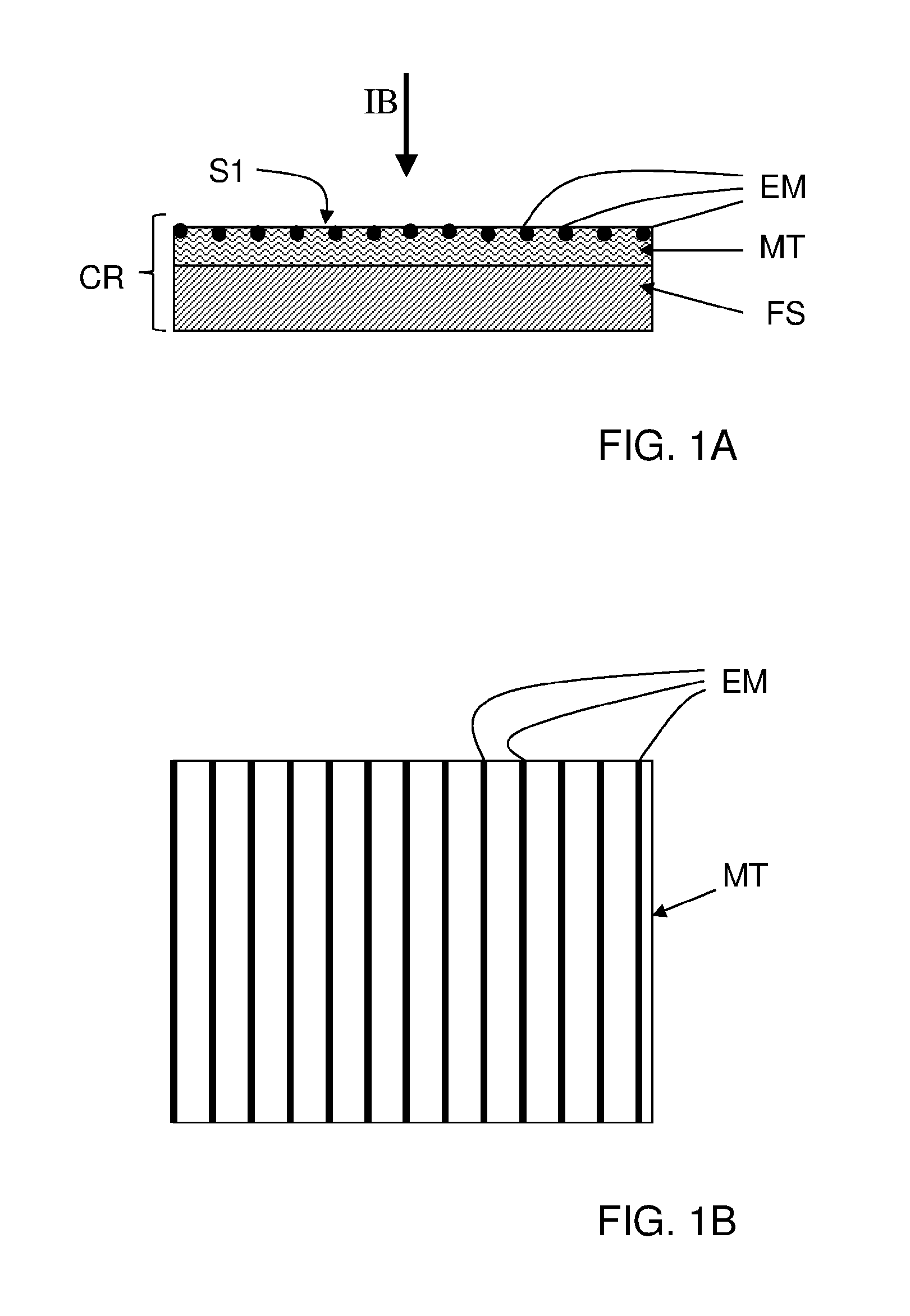
[0083]A carrier provided at a first side with an initial embedded patterned metal structure was prepared. To that end a 125 micron thick, thermally stabilized PEN foil from Dupont-Tejin films was used upon which a patterned metal structure was printed formed by a set of parallel lines having a width varying in the range of 100 to 2000 micron. The patterned metal structure was deposited on the PEN-foil by screen printing. A DEK Horizon 03i screen printer with a SD40 / 25 400 mesh screen was used for this purpose. Material Inktec TEC-PA-010 hybrid nano silver paste with a silver content of 55±10 wt % was used. This silver paste is a blend of silver nano particles and a soluble silver complex.

[0084]The patterned metal structure was embedded in an Ormostamp resist layer.

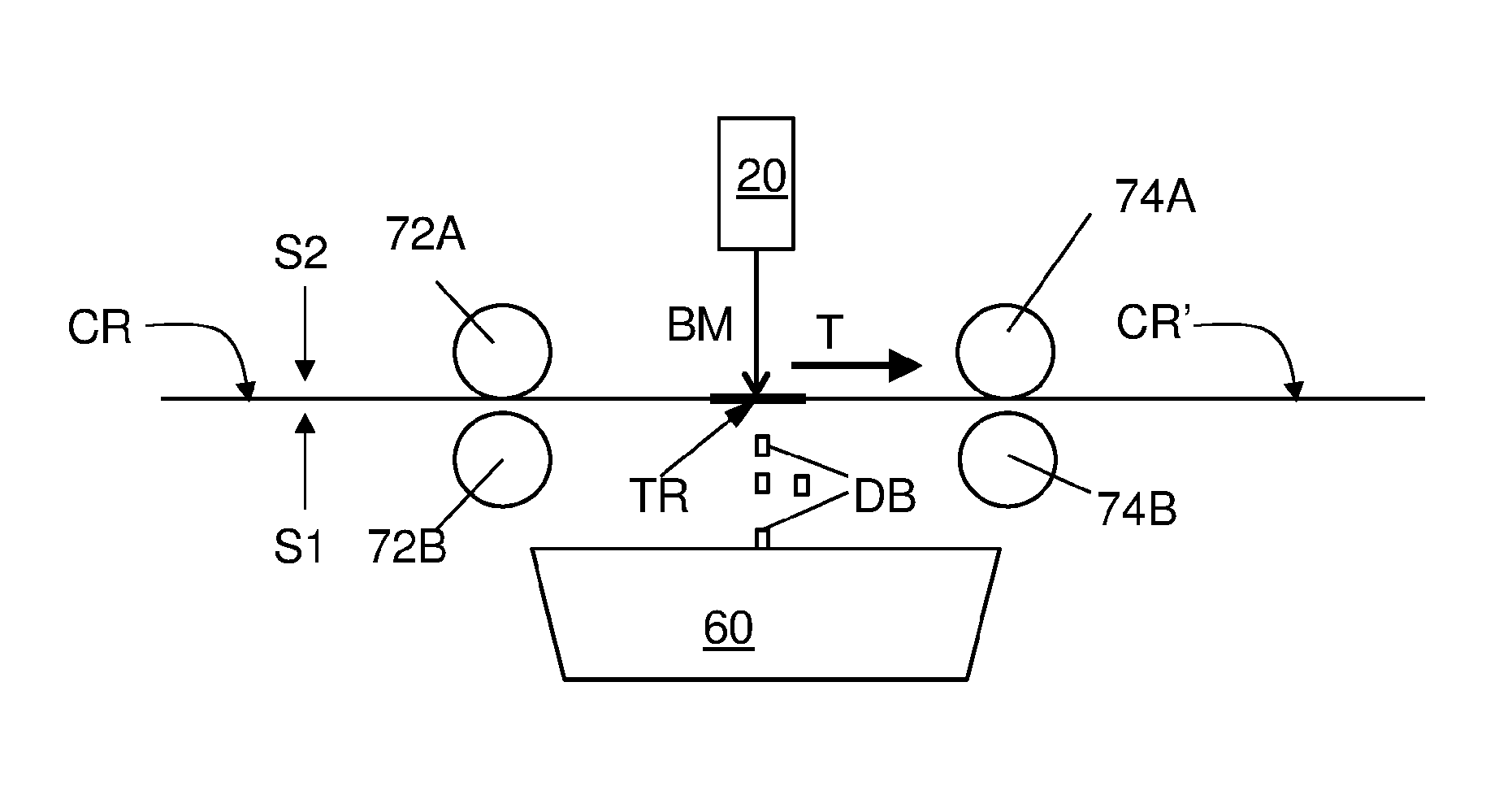
[0085]In a next step the carrier with the initial embedded patterned metal structure was irradiated at its second side opposite the first side with a radiation beam from a pulsed infrared laser, here a Nd-YAG laser with a ...

experiment 2

[0091]In this second example a Suntronic Ag based ink was used to apply an initial patterned metal structure with a thickness of 150 nm. A

[0092]Pixdro printer with Dimatix printer head was used for this purpose. The carrier in this case is a PEN foil with a moisture barrier having a WVTR of 10−6 g / m2 / day at its first side. The moisture barrier was formed as a stack subsequently comprising an inorganic layer, an organic layer and an inorganic layer. The inorganic layers are of silicon oxide having a thickness of 100 nm. The organic layer is an acrylate having a thickness of 5 micrometer. The printed pattern in this case involves a single line.

[0093]In a next step the carrier with the initial patterned metal structure was irradiated at its second side opposite the first side with a radiation beam from a pulsed infrared laser as specified above.

[0094]As a result of this treatment the resulting metal structure as shown in FIG. 8A was obtained. FIG. 8B shows a depth profile D3 obtained w...

experiment 3

[0095]As a counter example a similar sample was prepared as the one used for Example 2. However, in this case the carrier with the initial patterned metal structure was irradiated at its first side with a radiation beam from a pulsed infrared laser. In FIG. 9 it can be seen that the latter treatment causes damages to the surrounding material surrounding the location where metal is removed from the metal structure.


PUM

PropertyMeasurementUnit
wavelength bandaaaaaaaaaa
spot-sizeaaaaaaaaaa

Abstract

A method is presented for providing a carrier (CR) with an embedded patterned metal structure (EMM). The carrier at least includes a polymer foil (FS). The method comprise the steps of providing a carrier (CR) having a first side (S1) with an initial embedded patterned metal structure (EM). The carrier is then irradiated at a second side (S2) opposite the first side with a radiation beam (BM) that is at least partially transmitted through the carrier (CR) and at least partially absorbed by the initial embedded patterned metal structure (EM), therewith locally heating the initial embedded patterned metal structure and causing a removal of metal (DB) from the initial embedded patterned metal structure.

Description

BACKGROUND OF THE INVENTION[0001]1. Field of the invention[0002]The present invention relates to a method for providing a polymer foil with an embedded patterned metal structure.[0003]The present invention further relates to a system for providing a polymer foil with an embedded patterned metal structure.[0004]2. Related Art[0005]WO2010 / 016763 discloses a method of providing a polymer foil with an embedded patterned metal structure. The polymer foil prepared therewith can be used as a semi-finished product for manufacturing various electronic products, such as electro-optical products. Therein the embedded patterned metal structure may serve as an electronic conductor to support functioning of the product. This applies in particular to electro-optical products, which require at least one transparent electrode, such as an ITO-layer. The requirement of transparency puts restrictions on the thickness of the electrode, and therewith on its conductivity. Typically therefore the transpare...

Claims


Application Information

Patent Timeline
Patent Type & Authority Applications(United States)
IPC IPC(8): B23K26/00B23K26/57B23K26/0622B23K26/402H01L51/52B23K26/362
CPCB23K26/0063H01L51/5212B23K26/362B23K2203/172B23K26/402B23K26/57B23K2201/40B23K26/0624B23K26/40B23K26/361B23K2101/40B23K2103/16B23K2103/50B23K2103/172H10K50/814
Inventor ANDRIESSEN, HIERONYMUS ANTONIUS JOSEPHUS MARIAMANDAMPARAMBIL, RAJESHGILOT, JAN
Owner NEDERLANDSE ORG VOOR TOEGEPAST-NATUURWETENSCHAPPELIJK ONDERZOEK (TNO)
Why Eureka
Try Eureka