Substrate Carrier For Solar Cells

a solar cell and substrate technology, applied in the field of substrate carriers, can solve the problems of reducing material and the structure of conventional carriers are not strong enough to stand up to the test, and the yield of solar cells is reduced, so as to achieve the effect of superior hydrophobicity, high temperature and high cleanness

Inactive Publication Date: 2016-11-03
CHUNG KING ENTERPRISE CO LTD
View PDF27 Cites 11 Cited by
  • Summary
  • Abstract
  • Description
  • Claims
  • Application Information

AI Technical Summary

Benefits of technology

[0009]A main objective of the present invention is to provide a substrate carrier for solar cells that is made of a specific material having superior hydrophobicity capability, so as to achieve the characteristics of high temperature resistance, erosion resistance, high cleanness, low pollution (or low particle release), high hydrophobicity, and high abrasion resistance, thus increasing the lifetime of the carrier itself significantly. In this way, in particular, when the carrier is used to perform wet etching, due to the superior hydrophobicity of the carrier, not only can the residue etching fluids be reduced by 20%˜80% in volume, but a superb pyramid structure can also be formed (an acute angle greater than 20° can be formed between the reflection surface of the pyramid structure and the surface of the substrate) on the surface of solar cell substrate, so as to raise the photo-electric conversion efficiency of the solar cells according to the invention.
[0010]In the prior art, for the solar cell made through using the conventional carrier, the pyramid structure formed on the substrate may have an acute angle of less than 20°, so that the photo-electric conversion efficiency of solar cell thus made is less than 16%. However, in the present invention, for the solar cell made by using this type of new carrier, the acute angle of the pyramid structure can be formed greater than 20°, so as to raise its photo-electric conversion efficiency of the solar cell to about 17%˜25%.
[0012]In the present invention, the carrier made of PFA (Tetrafluoroethylene-perfluoroalkyl Vinyl Ether Copolymer) is suitable for a wet chemical etching process, and the carrier is provided with the characteristics of high temperature resistance, erosion resistance, high cleanliness, low pollution, and abrasion resistance, and thus raising its lifetime significantly. Meanwhile, through the provision of the inclined openings, the carrier is designed to have good hydrophobicity, thereby effectively preventing residue of etching fluid from remaining around the solar cell substrate, and thus restricting the pin mark or ineffective area around the substrate to less than 1 mm2. In addition, a superb pyramid structure is formed on the surface of solar cell substrate, with the angle between the reflection surface and the bottom surface of the pyramid structure greater than 20°, and thus raising the photo-electric conversion efficiency of solar cells thus made significantly.

Problems solved by technology

However, the material and the structure of the conventional carrier is not capable of withstanding strong acid and strong alkali etching fluids, and the high temperature incurred during such etching processes.
In other words, the conventional carrier is not capable of withstanding strong acid and strong alkali, and it can only endure process temperature of about 60° C.˜80° C. As such, it can only withstand acid / alkali etching fluid of low concentration (<20%), such that its lifetime is reduced, and it has to be replaced after 100˜500 times of usage.
In addition, hydrophobicity of the conventional carrier is rather insufficient, the residual etching fluid tends to remain around the solar cell substrate even after it has been rinsed, so after acid / alkali etching, the pin mark or invalid area around the solar cell substrate tends to be significantly large, so as to cause decrease of yield for the solar cells.
For example, due to insufficient hydrophobicity of the conventional carrier, the residues of strong alkali etching fluid in the previous step may still remain on the substrate, even after through the rinsing process.
As such, in case the substrates having strong alkali etching fluid residue thereon are transferred into the subsequent strong acid etching step, that could lead to acid-base neutralization, so as to adversely affect the result of substrate etching, and that could even endanger the life of the operator.
Therefore, the design and performance of a conventional substrate carrier is not quite satisfactory, and it leaves much room for improvement.

Method used


Image

  • Substrate Carrier For Solar Cells
  • Substrate Carrier For Solar Cells
  • Substrate Carrier For Solar Cells

Examples


first embodiment

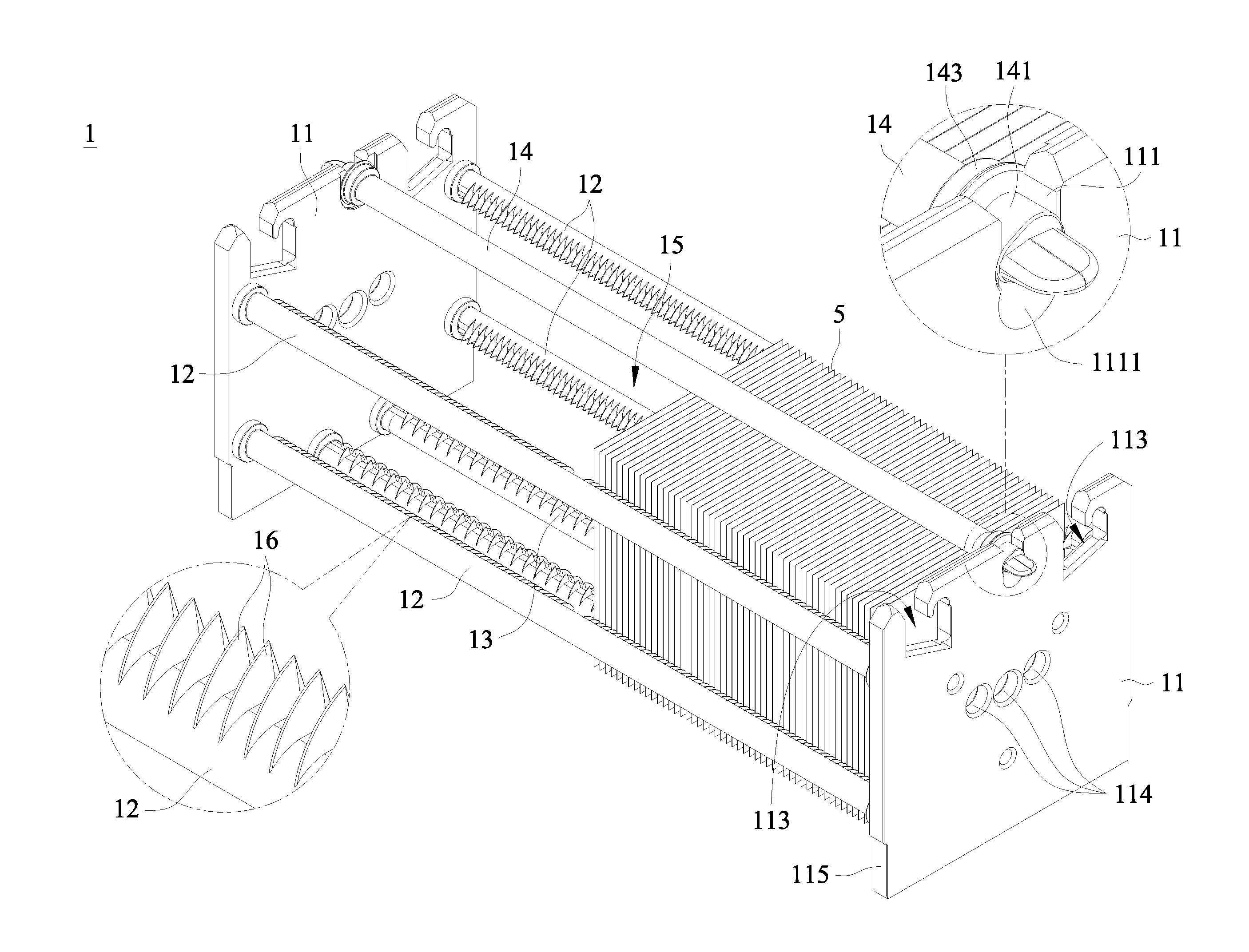
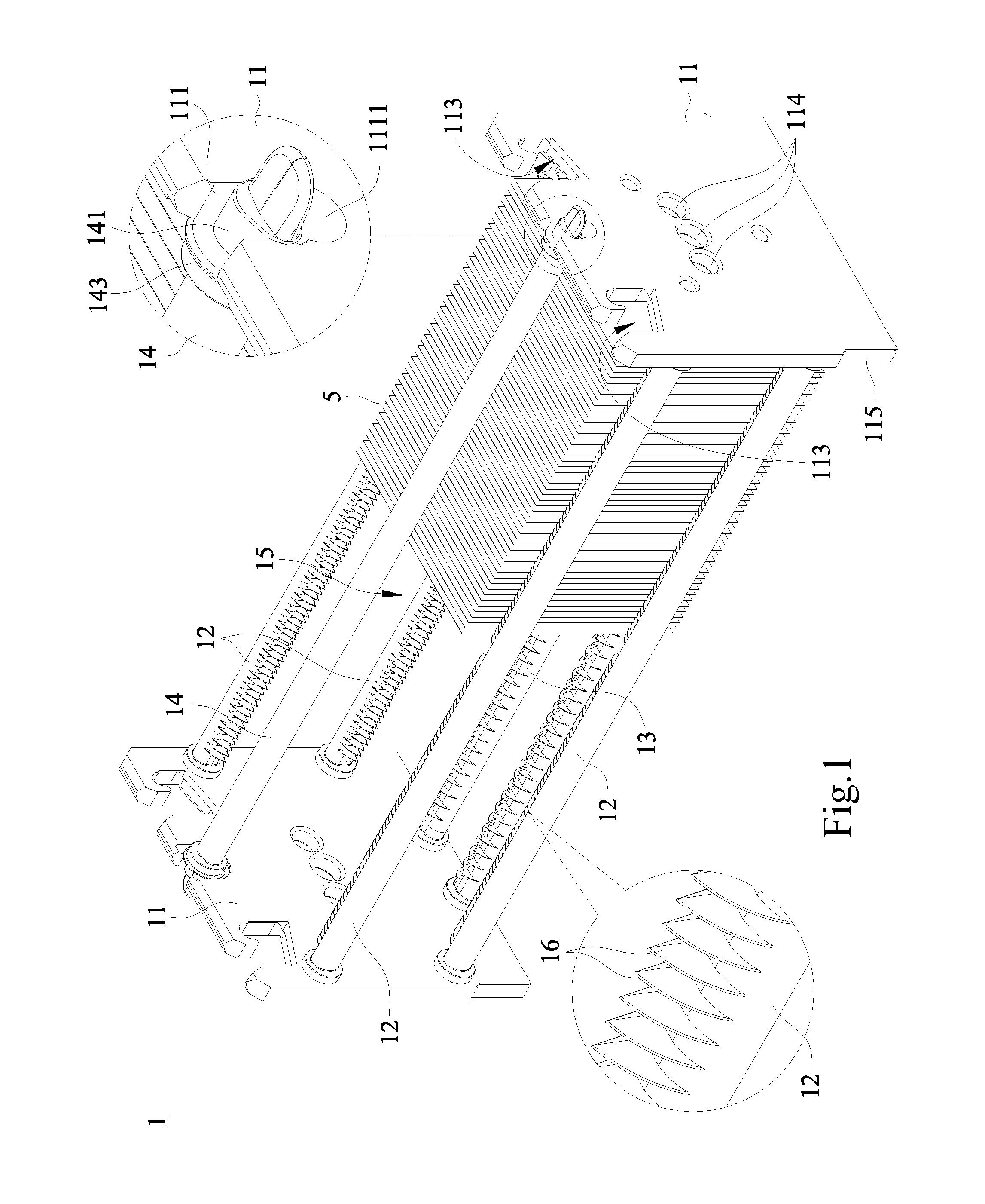
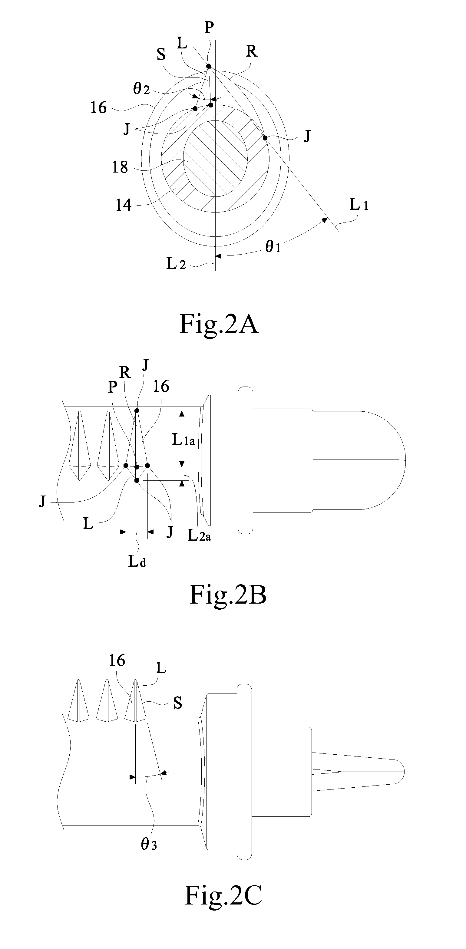
[0036]Refer to FIGS. 2A-2B for a side and a top views of first teeth according to the present invention. As shown in FIG. 2A, each of the first teeth 16, based on its side (axial) view, is formed by a longer arc edge R, a shorter line edge L, a pair of symmetric slant sides S, and an apex P. The apex P is defined as the highest point of the first teeth 16 (namely, located at the upper or far most part of the rod). As shown in FIG. 2B, each of the first teeth 16, based on its top (lengthwise) view, is connected to the side rod 12 and the press rod 14 respectively at the four junctions J, such that each of the first teeth 16 is able to support the respective solar cell substrate 5 through the pair of slant sides S (both Js located at the right and left positions of P) in a point-to-point contact manner.

[0037]Moreover, in the first embodiment, in the side view of the first teeth 16 is shown as an asymmetry fin. The radius of curvature of the arc edge R is between 3 mm and 500 mm. An an...

second embodiment

[0046]In the present invention, as shown in FIG. 4A, as viewed from the side, the first teeth 16 is in a form of an isosceles trapezoid, and is formed by a top face Ut, a pair of chamfer faces Ct, a pair of slant faces St, and a bottom portion. The chamfer face Ct has a radius of curvature between 1 mm and 30 mm. An angle θ5 is formed between a slant face St and a line Lt1 passing the center of the top face Ut and the center of the rod, and the angle θ5 has a range of 1°˜60°. Through the design of the size and angle of the structure mentioned above, the carrier is able to have optimal hydrophobicity, so that the solar cells thus produced could achieve the highest photo-electric conversion efficiency.

[0047]In the present embodiment, as shown in FIG. 4B, the first teeth 16 is shown in its front view as provided with the top face Ut, the chamfer face Ct, the slant face St, and the two slant side faces Bt. An angle θ6 is formed between the slant side face Bt and a line Lt2 passing the c...

third embodiment

[0048]Then, refer to FIG. 5A for a side view of a first teeth according to the present invention. As shown in FIG. 5A, the first teeth 16 are shown in its side view as an isosceles triangle having an apex P. The isosceles triangle is provided with two identical slant sides Si. An angle θ7 is formed by one of the slant sides, and a line L extending from the apex P to the center O of the rod (namely, the side rod 12, the bottom rod 13, or the press rod 14), and the angle θ7 has a range of 3°˜60°. Through the design of the size and angle of the structure mentioned above, the carrier is able to have optimal hydrophobicity, so that the solar cells thus produced could achieve the highest photo-electric conversion efficiency.

[0049]Refer to FIG. 5B for a top view of the first teeth according to the third embodiment of the present invention. As shown in FIG. 5B, the first teeth 16 are shown in its top view as a rhomb. The rhomb is shown with a maximum angle radial side F (radial side F facin...


PUM


Abstract

A substrate carrier for solar cells, utilized in a wet etching process, comprising: two side plates; at least a side rod, connected respectively to an outer portion on each side of the two side plates; at least a bottom rod, connected respectively to a lower portion on each side of the two side plates; at least a press rod, connected respectively to an upper portion on each side of the two side plates. Wherein, a space formed by formed by the two side plates, the side rod, the bottom rod, and press rod, is used to receive at least a solar cell substrate. Wherein, a plurality of first teeth are arranged axially along axes of the side rod and the press rod, such that each of the first teeth maintains a point-to-point contact with each of the solar cell substrates.

Description

BACKGROUND OF THE INVENTION[0001]1. Field of the Invention[0002]The present invention relates to a substrate carrier, and in particular to a substrate carrier for carrying and supporting solar cell substrates to perform wet etching in a manufacturing process, so as to form pyramid structure of superior quality on the surface of solar cell substrate, hereby raising the photo-electric conversion efficiency of the solar cells.[0003]2. The Prior Arts[0004]In the process of manufacturing solar cells, dry etching or wet etching is first performed, to form a pyramid structure on the surface of solar cell substrate, and that is used to produce a photo-electric conversion layer.[0005]In general, in the process of manufacturing solar cells, a carrier is used to carry and support solar cell substrates. Then, a robotic arm is provided to hold the carrier, to go through a variety of processes relating to acid and alkali etching, rinsing, and drying steps for the solar cell substrates contained t...

Claims


Application Information

Patent Timeline
Patent Type & Authority Applications(United States)
IPC IPC(8): H01L21/687H01L21/67
CPCH01L21/68785H01L21/68757H01L21/68771H01L21/68735H01L21/68778H01L21/67075H01L21/67313
Inventor YEN, HUI-CHAN
Owner CHUNG KING ENTERPRISE CO LTD
Why Eureka
Try Eureka