Method for producing metal containing composite and metal containing composite formed by adhesion

a metal containing composite and metal containing composite technology, which is applied in the direction of film/foil adhesives, adhesive types, layered products, etc., can solve the problem that the connection of bolts and nuts cannot be used to connect cfrps with one another, and the number of working steps required for forming through holes is beyond supposition, so as to achieve high adhesion strength

Active Publication Date: 2016-11-17
TAISEI PLAS CO LTD
View PDF2 Cites 9 Cited by
  • Summary
  • Abstract
  • Description
  • Claims
  • Application Information

AI Technical Summary

Benefits of technology

[0113]The present disclosure clarified ideal sectional surface configuration of metal materials for obtaining high shear strength of adhesion and tensile strength of adhesion for the adhesion of pieces comprising a metal or metals with a one-part epoxy adhesive according to New NAT theory, and further clarified the method for forming such surface configuration of a metal. At the same time, the disclosure clarified the maximum tensile strength of adhesion is substantially same as the tensile strength of the one-part epoxy adhesive itself. Consequently, complete adhesion or adhesion for all directions becomes possible with the present disclosure, and also the direction of study is shown here so as to make the strength of adhesion be of the maximum level if obtained strength of adhesion does not come to the level. In short, the present disclosure gives reliability as to what a strength level of adhesion joined with an adhesive can exhibit, whether it is adapted to practical use or not, or the like. As a result, it becomes possible to provide a new manufacturing method in the forthcoming industries of general machines, medical instruments, electrical machines, moving machines and other various kinds of machines.
[0114]FIG. 1(a) is a sectional schematic view for explaining the principle of the present disclosure and for showing surface configuration of the metal part as “treated according to NAT” in the face of adhesion with cured adhesive in section.
[0115]FIG. 1(b) is a sectional schematic view for explaining the principle of the present disclosure and for showing surface configuration of the metal part of “ultrafine concaves of bowl shape” in the face of adhesion with cured adhesive in section.
[0116]FIG. 1(c) is a sectional schematic view for explaining the principle of the present disclosure and for showing surface configuration of the metal part of “V-shaped valley type” in the face of adhesion with cured adhesive in section.
[0117]FIG. 1(d) is a sectional schematic view for explaining the principle of the present disclosure and for showing surface configuration of the metal part of “step-like shape” in the face of adhesion with cured adhesive in section.
[0118]FIG. 1(e) is a sectional schematic view for explaining the principle of the present disclosure and for showing surface configuration of the metal part of “shape of mountains on a plain” in the face of adhesion with cured adhesive in section.

Problems solved by technology

Due to this, bolt and nut connection cannot be used for connecting CFRP with another member of a metal part or the like.
However, it is not an easy matter to perform precision working of two kinds of CFRP members to be connected so that the diameters of the through-holes formed therein are in the level of “rivet diameter+0.1 mm”.
Further, tremendous number of rivets is necessary for manufacturing an aircraft and the number of working steps required for forming through-holes is beyond supposition.
However, there has not been sufficient development of a method or theoretical explanation for this yet.
However, this specimen exhibited an inferiority such that there is much dispersion in data of measurement because bending moment is apt to be applied on the specimen depending on a manner of fastening, with chucks, the both gripped ends of specimen comprising two joined small pieces with total length of 36 mm when the specimen is to be pulled off in a tensile test.
While dispersion is apt to occur and seems to be of a level in the mean value higher than stainless steel as a result, there is an inferiority in a simple configuration of step-like irregularities itself.
While it was a question how this acts on adhesion strength, both “shear strength of adhesion” and “tensile strength of adhesion” were low as a result.
However, such sectional configuration of materials subjected to surface treatment has not been found yet.
But sorry to say, the inventor has not succeeded yet in forming copper pieces that have such presumed shortened whiskers like a head with close cropped hairs.
But the trial was reduced to a failure.
But, it is originally difficult to form a cured adhesive that is formed through shaping an adhesive itself and is absolutely free of void.
Although it is also considered that it is possible by injecting the adhesive into a metallic mold coated with TEFRON (polytetrafluoroethylene; trade mark), using an injection molding machine for thermosetting resin, such experiment will probably cause the injection molding machine to be spoiled.
In short, verification is not sufficient in this respect.

Method used


Image

  • Method for producing metal containing composite and metal containing composite formed by adhesion
  • Method for producing metal containing composite and metal containing composite formed by adhesion
  • Method for producing metal containing composite and metal containing composite formed by adhesion

Examples


experiment example 1

NAT Treatment of Al-Alloy

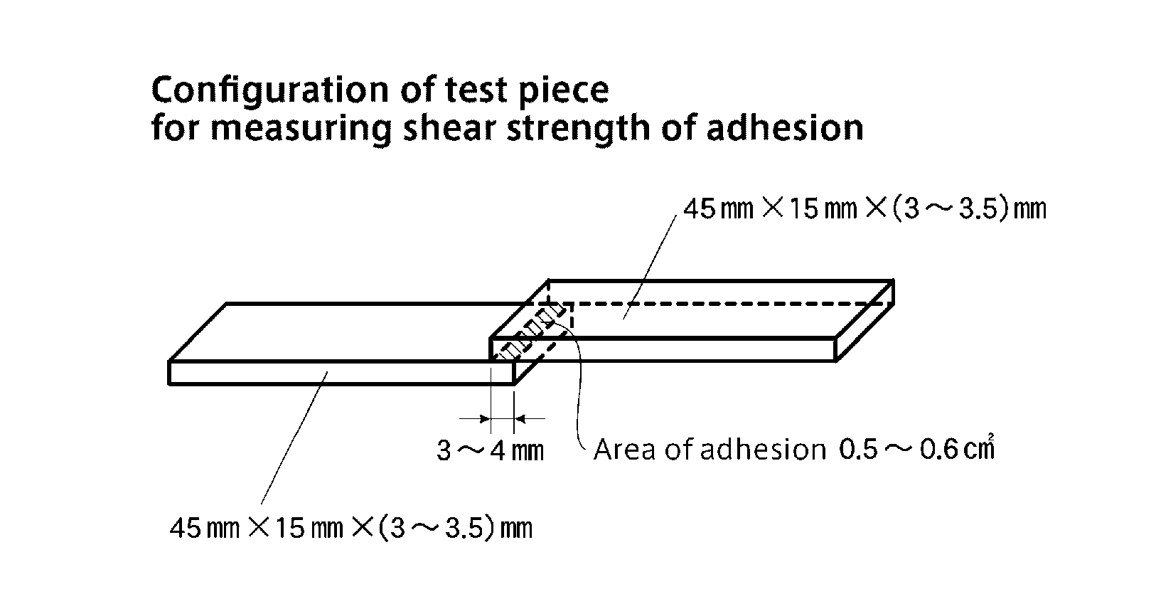
[0187]Sheet stocks of Al-alloy A7075 having a thickness of 3 mm were acquired and machined to form a plurality of small pieces with a dimension of 45 mm×15 mm×3 mm. Further, a plurality of small pieces with a dimension of 100 mm×25 mm×3 mm were formed by machining from the same Al-alloy sheet stocks. An aqueous solution containing degreaser for aluminum “NE-6” (made by Meltex co. Ltd., main company in Tobkyo, Japan) by 10% was made ready to be at 60° C. in a tank, in which the above alloy pieces were immersed for 5 minutes, and after then the pieces were rinsed with tap water (Ota city, Gumma prefecture, Japan). Next, an aqueous solution of hydrochloric acid having a concentration of 1% was made ready to be at 40° C. in another tank, in which the pieces were immersed for 1 minute and after then the pieces were rinsed with water. Next, an aqueous solution of caustic soda having a concentration of 1.5% was made ready to be at 40° C. in still another tank, in w...

experiment example 2

New NAT Treatment of Al-Alloy

[0189]Sheet stocks of Al-alloy A7075 having a thickness of 3 mm were acquired and machined to form a plurality of small pieces with a dimension of 45 mm×15 mm×3 mm. Further, a plurality of small pieces with a dimension of 100 mm×25 mm×3 mm were formed by machining from the same Al-alloy sheet stocks. An aqueous solution containing degreaser for aluminum “NE-6” by 10% was made ready to be at 60° C. in a tank, in which the above alloy pieces were immersed for 5 minutes, and after then the pieces were rinsed with tap water (Ota city, Gumma prefecture, Japan). Next, an aqueous solution of hydrochloric acid having a concentration of 1% was made ready to be at 40° C. in another tank, in which the pieces were immersed for 1 minute and after then the pieces were rinsed with water. Next, an aqueous solution of caustic soda having a concentration of 1.5% was made ready to be at 40° C., in which the alloy pieces were immersed for 4 minutes and after then rinsed wit...

experiment example 3

NAT Treatment of Stainless Steel (Referential Example)

[0191]Sheet stocks of stainless steel SUS304 having a thickness of 3 mm were acquired and machined to form a plurality of small pieces with a dimension of 45 mm×15 mm×3 mm. Further, a plurality of small pieces with a dimension of 100 mm×25 mm×3 mm were formed by machining from the same stainless sheet stocks. An aqueous solution containing degreaser for aluminum “NE-6” (made by Meltex co. Ltd., main company in Tokyo, Japan) by 10% was made ready to be at 60° C. in a tank, in which the above steel pieces were immersed for 5 minutes, and after then the pieces were rinsed with tap water (Ota city, Gumma prefecture, Japan). Next, an aqueous solution of caustic soda having a concentration of 1.5% was made ready to be at 40° C. in another tank, in which the steel pieces were immersed for 1 minute and after then rinsed with tap water. Next, an aqueous solution of sulfuric acid having a concentration of 5% was made ready to be at 65° C.,...


PUM

PropertyMeasurementUnit
diameteraaaaaaaaaa
temperatureaaaaaaaaaa
heightaaaaaaaaaa

Abstract

An adhesive (B) of solvent containing adhesive as a suspension of low viscosity is prepared by adding a solvent MIBK to a one-part epoxy adhesive of a dicyandiamide-curable type (A). Metal shaped articles (M1 to M5) as adherends are prepared each of which, through various surface treatment, has specific surface configuration of roughened face and/or ultrafine irregularities and the surface is entirely covered with a thin layer of ceramics such as a metal oxide or metal phosphate. The specified face of each metal shaped article (M1 to M5) is painted with the solvent containing adhesive (B). The faces painted with the adhesive of two metal shaped articles (M1 to M5) are caused to abut each other, the articles are heated to cure the one-epoxy adhesive to accomplish adhesion. With one of the adherends replaced by a CFRP shaped article (P2), a composite of a metal and CFRP can be formed.

Description

CROSS REFERENCE TO RELATED APPLICATIONS[0001]This application is based on and claims priority under 35 U.S.C. §119 to Japanese Patent Application No. 2015-97750, filed on May 12, 2015, the entire content of which is incorporated herein by reference.TECHNICAL FIELD[0002]The present disclosure relates to a method for producing a metal containing composite and to a metal containing composite formed by adhesion. More particularly, the present disclosure relates to techniques for strongly integrating, by use of an epoxy adhesive, a metal part with another metal part or a metal part with a CFRP (Carbon Fiber Reinforced Plastic) part and provides practical use of a method for integrating a metal part with another metal part or a metal part with a CFRP part in place of an assembling method with bolt and nut, by welding, by tight fitting or the like. The present disclosure deals with all kinds of metal including copper, steel, magnesium alloy, aluminum alloy, titanium alloy or the like and c...

Claims


Application Information

Patent Timeline
Patent Type & Authority Applications(United States)
IPC IPC(8): C09J7/02
CPCC09J7/0292C09J2463/00C09J2400/163C09J2201/122C09J5/06C09J163/00B29C65/4835B29C65/526B29C65/8215B29C65/8253B29C66/0222B29C66/02245B29C66/0242B29C66/112B29C66/114B29C66/1142B29C66/30322B29C66/43B29C66/43421B29C66/43441B29C66/71B29C66/7212B29C66/73161B29C66/73751B29C66/73755B29C66/7394B29C66/742B29C66/7422B29C66/7428B29C66/74281B29C66/74283B29C66/919B29C65/02B29C66/72141C23C22/05C23C22/33C23C22/57C23C22/63C23C22/64C23F1/18C23F1/20C23F1/28C23F1/40C23G1/00C23G1/125C23G1/22B32B7/12B29K2307/04B29K2063/00B29C65/00
Inventor ANDOH, NAOKI
Owner TAISEI PLAS CO LTD
Why Eureka
Try Eureka