Method of solvent recovery from a dilute solution

a solvent recovery and dilute solution technology, applied in the field of liquid processing systems and methods, can solve the problems of low recovery ratio, large amount of effluents that have a negative impact on the environment, and conventional reverse osmosis (ro) processes suffer from certain challenges, and achieve high rejection membranes and reduce the pressure gradient across the membrane.

Active Publication Date: 2016-11-24
AL BAKRI SAMI ABDULRAHMAN
View PDF6 Cites 18 Cited by
  • Summary
  • Abstract
  • Description
  • Claims
  • Application Information

AI Technical Summary

Benefits of technology

[0010]The first phase reverse osmosis units are arranged in series with one another from a first reverse osmosis unit to a last reverse osmosis unit. Each of the first phase reverse osmosis units has a concentrate side, a permeate side, and a reverse osmosis membrane separating the concentrate side from the permeate side. The first phase reverse osmosis units maintain a small differential of concentration of ions across the membrane by using low rejection membranes and / or passing brine from the concentrate side to the permeate side to form a mixed permeate. This small differential in ion concentration reduces the pressure gradient across the membrane. The mixed permeate from the first reverse osmosis unit is fed to the final phase reverse osmosis unit. The final phase reverse osmosis unit includes a high rejection membrane and produces pure solvent.

Problems solved by technology

Conventional desalination of sea or brackish water is an energy intensive process that has a low recovery ratio and produces large amounts of effluents that have a negative impact on the environment.
However, conventional reverse osmosis (RO) processes suffer from certain challenges that include low recovery ratio and membrane scaling.
These two challenges control the economics of RO desalination and concentrating dilute solutions and both of them are related to pressure across the membrane.
In addition, increased pressure across the membranes requires costly membrane assemblies and higher power consumption.

Method used


Image

  • Method of solvent recovery from a dilute solution
  • Method of solvent recovery from a dilute solution
  • Method of solvent recovery from a dilute solution

Examples


third embodiment

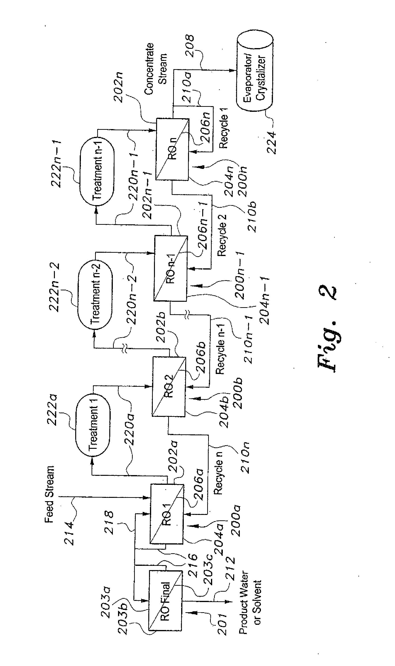
[0036]FIG. 3 further includes a metals and solids recovery device 334 that receives and processes concentrate from the concentrate side 328 of the nanofiltration device 326 via an interconnecting line 320a, with a water and / or solvent recovery device 336 receiving and processing liquid output from the metals and solids recovery device 334 via an interconnecting line 320b. Processed water or solvent is delivered from the system by a line 320c from the water and / or solvent recovery device 336, and by a line 320d from the evaporator / crystallizer device 324. Processed solids and / or concentrate are removed from the system by output 308a from the metals and solids recovery device 334, and by output 308 b from the evaporator / crystallizer device 324. The two outputs 308a, 308b may extend to a single output destination, similarly to the two lines 320c and 320d that extend to a single product water or solvent collection point.

[0037]FIG. 4 of the drawings provides a schematic illustration of a...

sixth embodiment

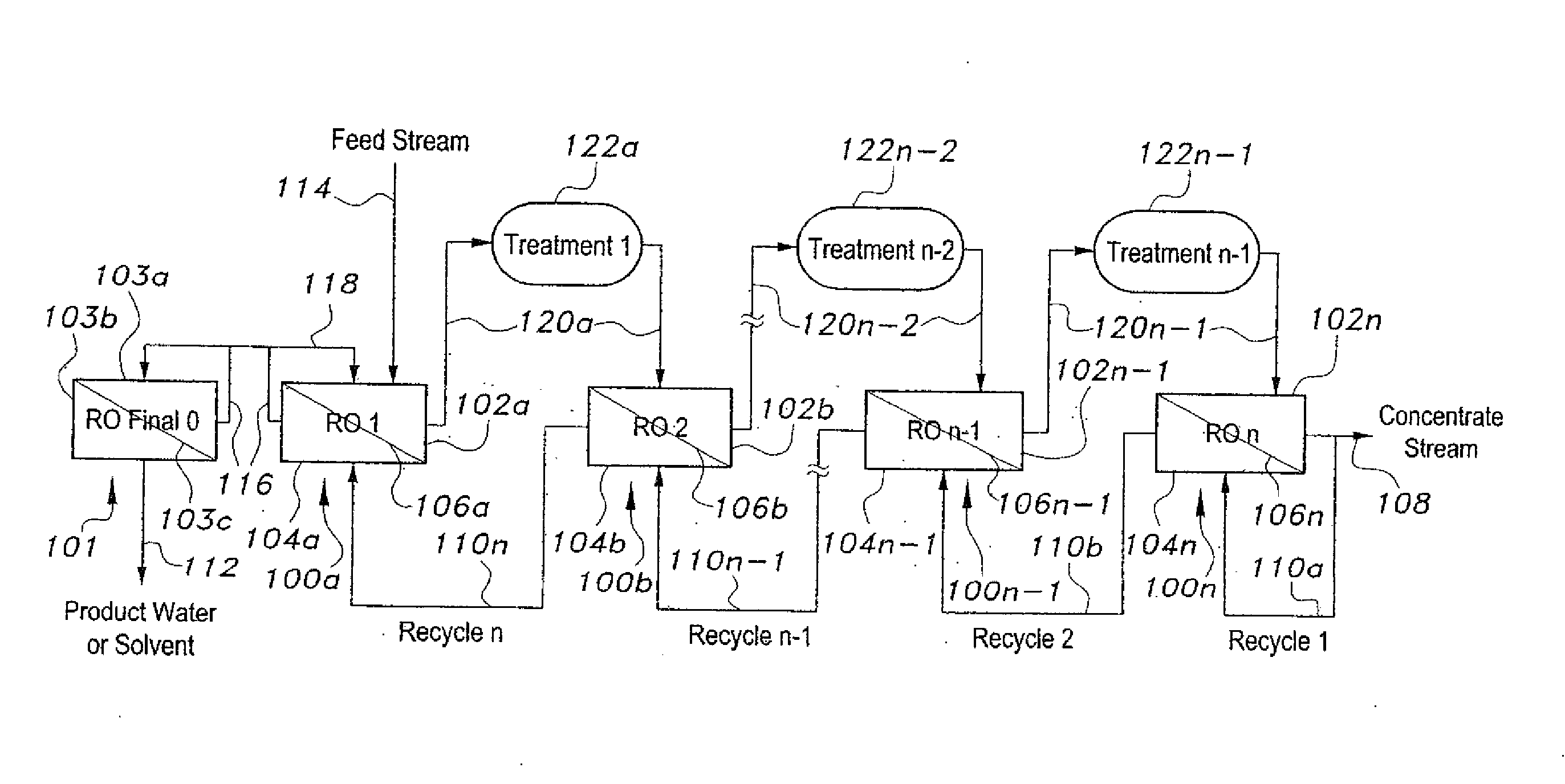
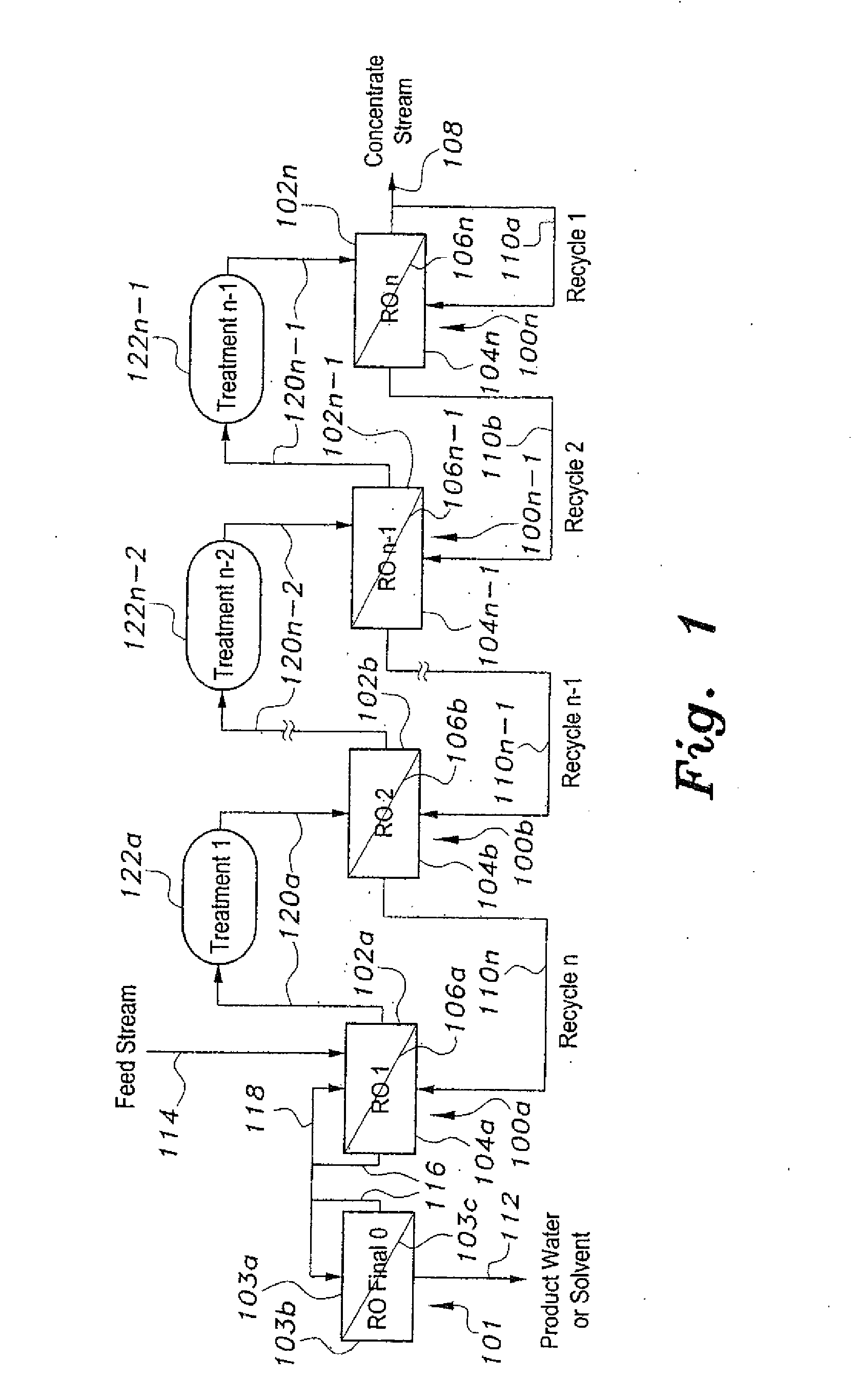
[0044]FIG. 6 of the drawings provides a schematic illustration of the method of solvent recovery. The embodiment of FIG. 6 differs from previous embodiments described further above and illustrated in FIGS. 1 through 5 primarily in that the stages 600a through 600n of the embodiment of FIG. 6 are forward osmosis devices, rather than reverse osmosis units. Each of the forward osmosis stages 600a through 600n includes a concentrate side, respectively 602a through 602n, a permeate side, respectively 604a through 604n, and a forward osmosis (FO) membrane, respectively 606a through 606n, separating the concentrate and permeate sides of each forward osmosis unit.

[0045]FO systems differ from RO systems in that in the case of forward osmosis, very little differential pressure is required to drive the solute across the membrane, e.g., 606a for the first unit 600a, from its concentrate side 602a to its permeate side 604a. Rather, the transfer of solute across the membrane is dependent upon nat...

first embodiment

[0047]Rather than passing a portion of the concentrate stream from the concentrate side of the final osmosis stage back to the permeate side of that stage, as in FIG. 1, the concentrate stream 608 of the forward osmosis embodiment of FIG. 6 is not remixed with any of the liquid concentrate or permeate of the system after being discharged from the concentrate side 602n of the final forward osmosis stage 600n. The forward osmosis system embodiment of FIG. 6 uses a draw solution of higher concentrate than the concentrate resulting in the concentrate side 602n of the final forward osmosis stage 600n. This draw solution enters the system through a first draw solution line 610a to the permeate side 604n of the final forward osmosis stage 600n. The draw solution is diluted by osmotic flow through the membrane 606n to the permeate side 604n of the final stage 600n. The diluted draw and permeate solution then flows from the permeate side 604n of the final stage 600n, to the permeate side 604...


PUM

PropertyMeasurementUnit
solventaaaaaaaaaa
concentrationaaaaaaaaaa
pressureaaaaaaaaaa

Abstract

The method of solvent recovery includes using a plurality of solvent recovery units to recover solvent from a dilute solution. The solvent recovery units can include a plurality of reverse osmosis or forward osmosis membrane systems arranged in series. For reverse osmosis, at least some of the concentrate in a last reverse osmosis unit of the series is recycled back to the permeate of that unit to provide a mixed permeate. The mixed permeate is then passed successively to the permeate side of each preceding reverse osmosis unit in the series. For forward osmosis, a draw solution is passed sequentially from the permeate side of each unit to the permeate side of the preceding unit. The draw solution may be prepared by concentrating part of the concentrate stream by evaporation and recycling it back as a draw solution.

Description

REFERENCE TO RELATED APPLICATION[0001]This application is a division of U.S. patent application Ser. No. 14 / 932,872 filed on Nov. 4, 2015, which application is a continuation-in-part of U.S. patent application Ser. No. 14 / 720,666 filed on May 22, 2015.BACKGROUND OF THE INVENTION[0002]1. Field of the Invention[0003]The present invention relates generally to liquid processing systems and methods, and particularly to a method of solvent recovery from a dilute solution.[0004]2. Description of the Related Art[0005]Many solutions that exist in nature or that are produced by industrial processes or as waste streams are dilute. Sea water, for example, includes 3%-5% salts and 95%-97% water, while brackish water contains much more water and less dissolved solids. Conventional desalination of sea or brackish water is an energy intensive process that has a low recovery ratio and produces large amounts of effluents that have a negative impact on the environment. Milk includes 87%-91% water, and...

Claims


Application Information

Patent Timeline
Patent Type & Authority Applications(United States)
IPC IPC(8): B01D61/58B01D61/02B01D61/42C02F1/44A23L2/08C02F9/00C02F1/52C02F1/04A23C9/142B01D61/00C02F1/469
CPCB01D61/58B01D2317/022B01D61/027B01D61/422C02F1/442C02F1/445C02F1/4693C02F9/00C02F1/5281C02F1/04A23C9/1427A23L2/085C02F2001/5218C02F2101/10C02F2103/28A23V2002/00B01D2311/12B01D2311/2649B01D2311/2673B01D61/002B01D61/025B01D2311/08C02F2301/08C02F1/441B01D61/026B01D61/0021B01D2311/25B01D2311/04B01D61/10
Inventor ABUSHARKH, BASEL
Owner AL BAKRI SAMI ABDULRAHMAN
Why Eureka
Try Eureka