Systems and Methods for Dynamic Energy Distribution

a dynamic energy and energy distribution technology, applied in the energy industry, transportation and packaging, sustainable buildings, etc., can solve the problems of inconvenient or undesirable attachment of iot devices to a conventional power grid, recharging or replacing batteries, becoming a major challenge in terms of time consumption or material and labor costs

Inactive Publication Date: 2016-12-08
JIN RUXIANG
View PDF7 Cites 28 Cited by
  • Summary
  • Abstract
  • Description
  • Claims
  • Application Information

AI Technical Summary

Benefits of technology

[0012]The present invention provides methods and network systems for energy distribution and storage among a plurality of spatially separated sites. An example embodiment of said method comprises dynamically allocating photovoltaic energy to light emitters comprising optical gain media pumped by filtered sunlight power or photovoltaic power, allocating a certain amount of power to each emitter, and delivering light-beam energy from one site to a plurality of sites equipped with light power rece

Problems solved by technology

However in many cases it may be either inconvenient or undesirable to attach IOT devices to a conventional power grid.
As the number of IOT devices located at different sites increase rapidly, locating, recharging, or replacing the batteries in IOT devices scattered in potentially diverse geographical locations is becoming a major challenge in terms of time consumption or material and labor cost.
In conventional wired distribution systems, the sites connected by a power grid are mostly stationary, meaning that the spatial locations of the sites are fixed in most cases, and the number and the location of the sites cannot be changed easily in real time.
For example, a solar power generation site may lose its ability to supply power to other sites of the wired grid if the weather conditions at the solar site are rainy or cloudy for an extended time p

Method used


Image

  • Systems and Methods for Dynamic Energy Distribution
  • Systems and Methods for Dynamic Energy Distribution
  • Systems and Methods for Dynamic Energy Distribution

Examples


Embodiment Construction

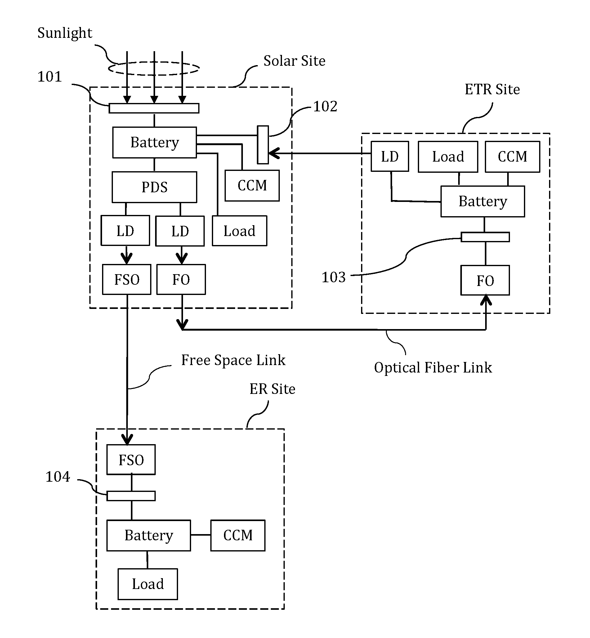
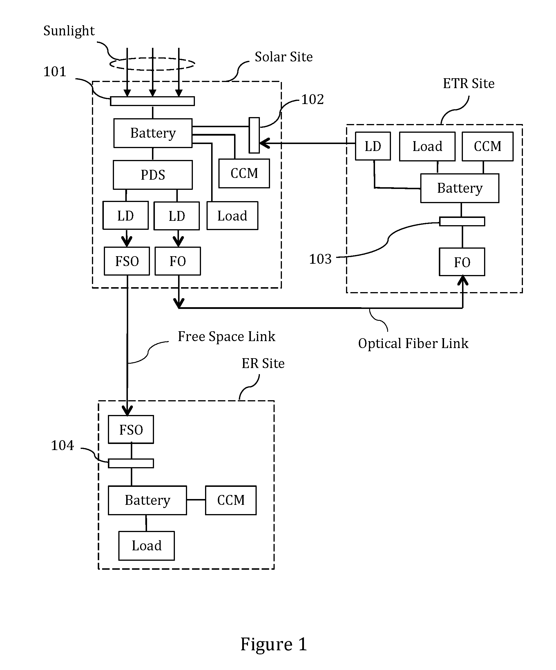
[0021]FIG. 1 shows, by way of example, an embodiment of the energy distribution system of the current invention. A solar site comprises a solar cell 101 that converts sunlight energy to electrical energy to charge a battery that supplies power to other devices and electrical loads at the site. The solar site battery can also be charged by receiving and converting optical power delivered from a spatially separate energy transmitting-receiving (ETR) site using a light-power receiver 102 that converts light energy to electrical energy. An optical fiber link and a free space link connect the solar site to the ETR site and to a separate energy-receiving (ER) site, respectively. Energy at the solar site is delivered to the ETR site by first coupling the light beam from a laser diode (LD) into an optical fiber using fiber optics (FO) components, and then transmitting the fiber-coupled light beam to the ETR site via an optical fiber link between the solar site and the ETR site. The FO compo...


PUM


Abstract

A dynamic network for energy-distribution can comprise energy converters, communication-and-control modules, power distribution switches, energy storage batteries, light emitters and light receivers located at spatially separated sites connected by optical transmission media, wherein each site can be equipped with energy transmitting, receiving or storage functionalities as well as signal-communication functionalities. The topology of the energy-distribution network can be changed dynamically by activating or deactivating optical links among the sites via software control. Charging vehicles can act as moving sites to remotely deliver energy to or receive energy from devices located at different sites of a network.

Description

CROSS-REFERENCE TO RELATED APPLICATIONS[0001]This application claims the benefit of the date of provisional patent application No. 62 / 172,086 (Jun. 6, 2015).STATEMENT REGARDING FEDERALLY SPONSORED RESEARCH OR DEVELOPMENT (IF APPLICABLE)[0002]The invention was NOT made by an agency of the United States Government or under a contract with an agency of the United States Government.REFERENCE TO SEQUENCE LISTING, A TABLE, OR A COMPUTER PROGRAM LISTING[0003]Not applicable.COMPACT DISC APPENDIX (IF APPLICABLE)[0004]Not applicable.BACKGROUND OF THE INVENTION[0005]The present invention relates to systems and methods for allocating energy among a plurality of devices or equipment located at different sites. In particular, the present invention relates to methods and systems to dynamically distribute and store energy among a plurality of spatially separated sites in a communication- and energy distribution network.[0006]The rapidly expanding Internet-of-Things (IOT) typically comprises an incr...

Claims


Application Information

Patent Timeline
IPC IPC(8): H02J3/38H02J50/30H02J7/35
CPCH02J3/383H02J50/30H02J7/35H02J50/50H02J2310/44Y02B10/10Y02P80/20Y02T90/167Y04S30/12
Inventor JIN, RUXIANG
Owner JIN RUXIANG
Why Eureka
Try Eureka