Eureka AIR delivers breakthrough ideas for toughest innovation challenges, trusted by R&D personnel around the world.

In-situ plasma cleaning of process chamber components

Active Publication Date: 2016-12-15
VARIAN SEMICON EQUIP ASSOC INC
View PDF6 Cites 18 Cited by
  • Summary
  • Abstract
  • Description
  • Claims
  • Application Information

AI Technical Summary

Benefits of technology

This patent is about systems and methods for cleaning ion implantation system components using plasma. The methods allow for quick and in-situ cleaning without the need for venting or manual cleaning. The plasma is generated locally around the components to be cleaned, reducing unwanted etching of other components. The technical effects are improved efficiency and effectiveness in ion implantation system maintenance.

Problems solved by technology

These residues build up on the beam-line components, causing spikes in the DC potentials during operation (e.g., in the case of electrically biased components).
Eventually the residues flake off, causing an increased likelihood of particulate contamination on the wafer.
Accordingly, these maintenance processes may be very time consuming.
In addition, the beam-line component is not used during the maintenance processes.
As such, frequent maintenance processes may decrease the time available for IC production, thus increasing overall manufacturing cost.

Method used


Image

  • In-situ plasma cleaning of process chamber components
  • In-situ plasma cleaning of process chamber components
  • In-situ plasma cleaning of process chamber components

Examples


Embodiment Construction

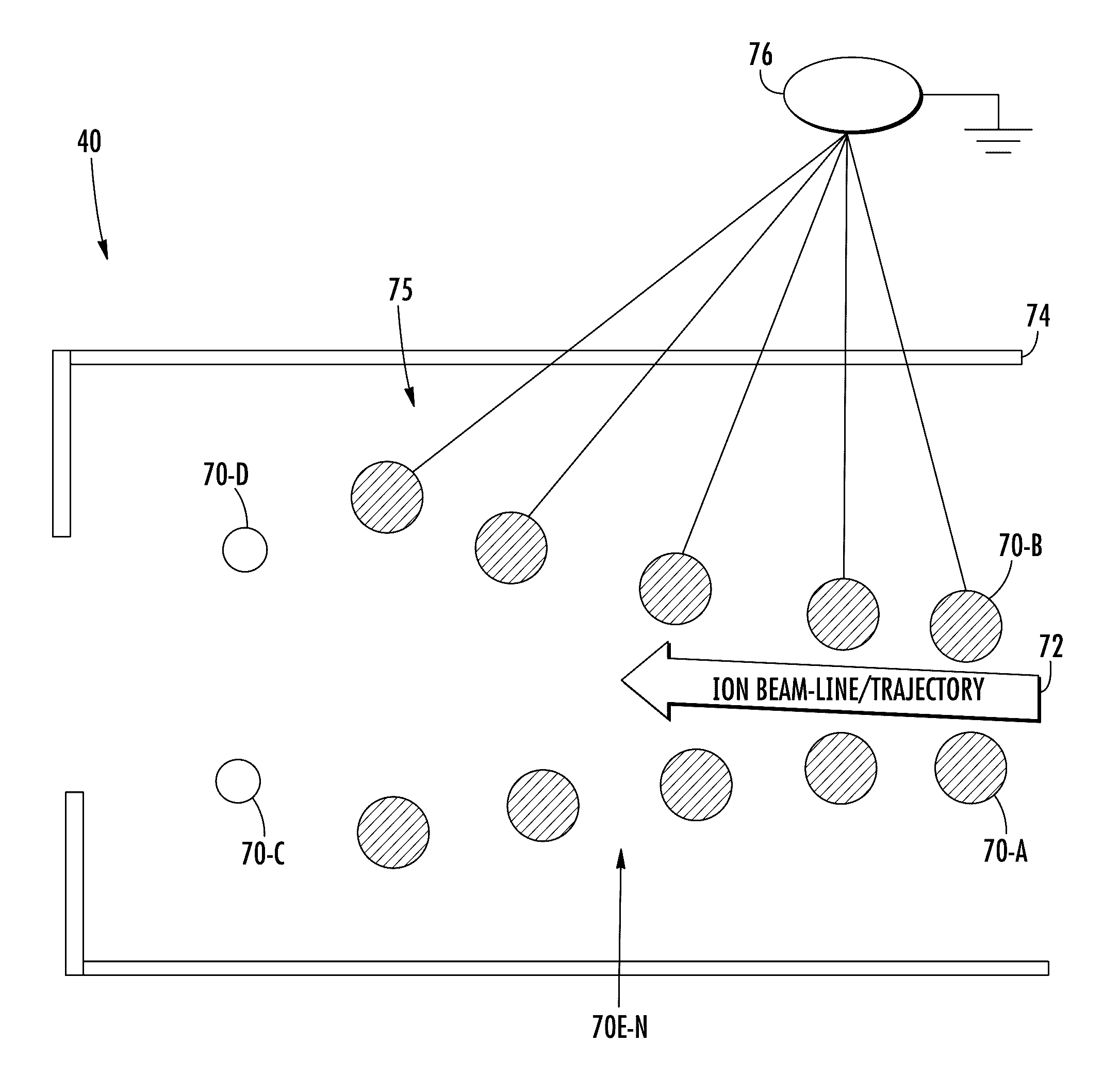
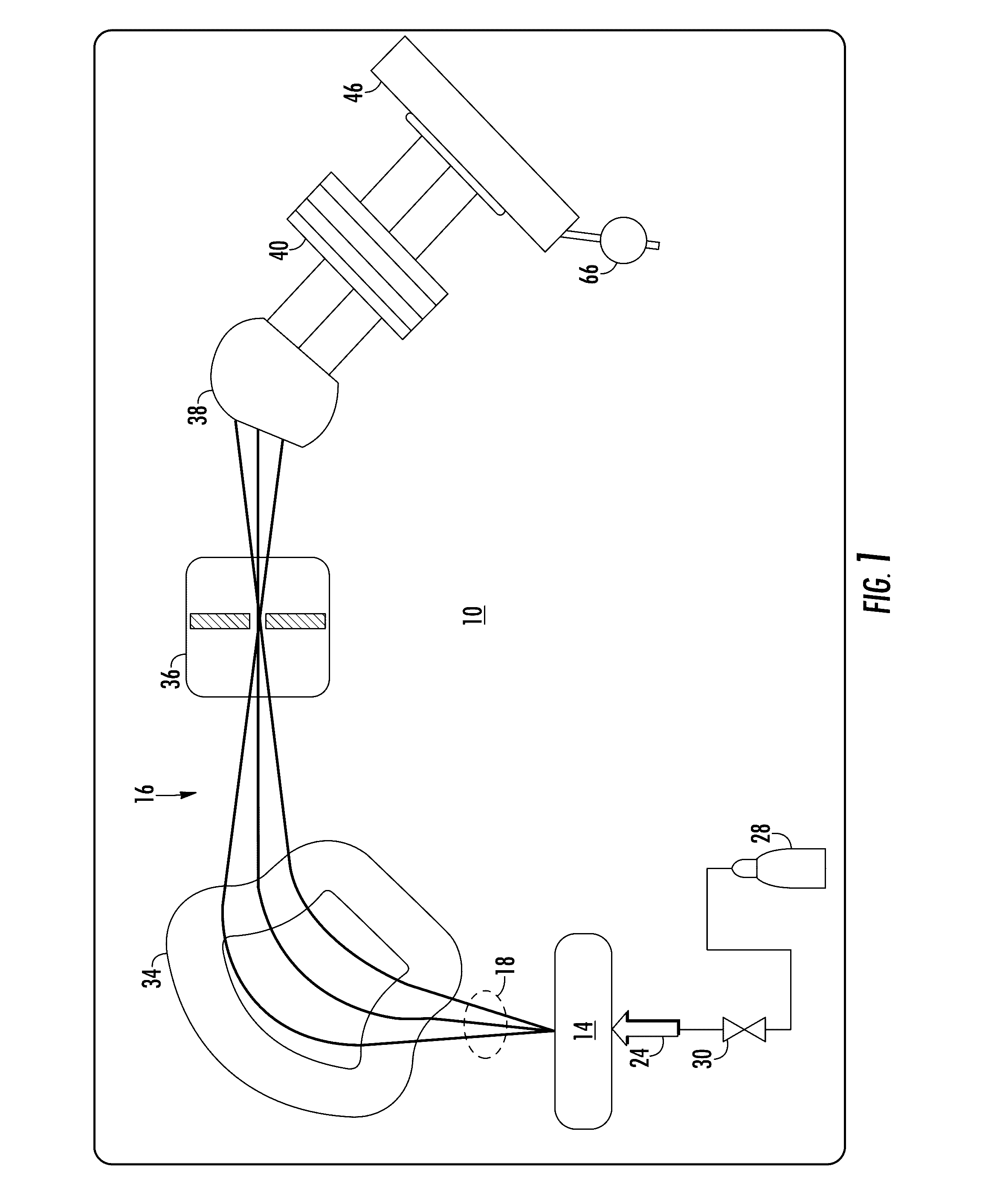
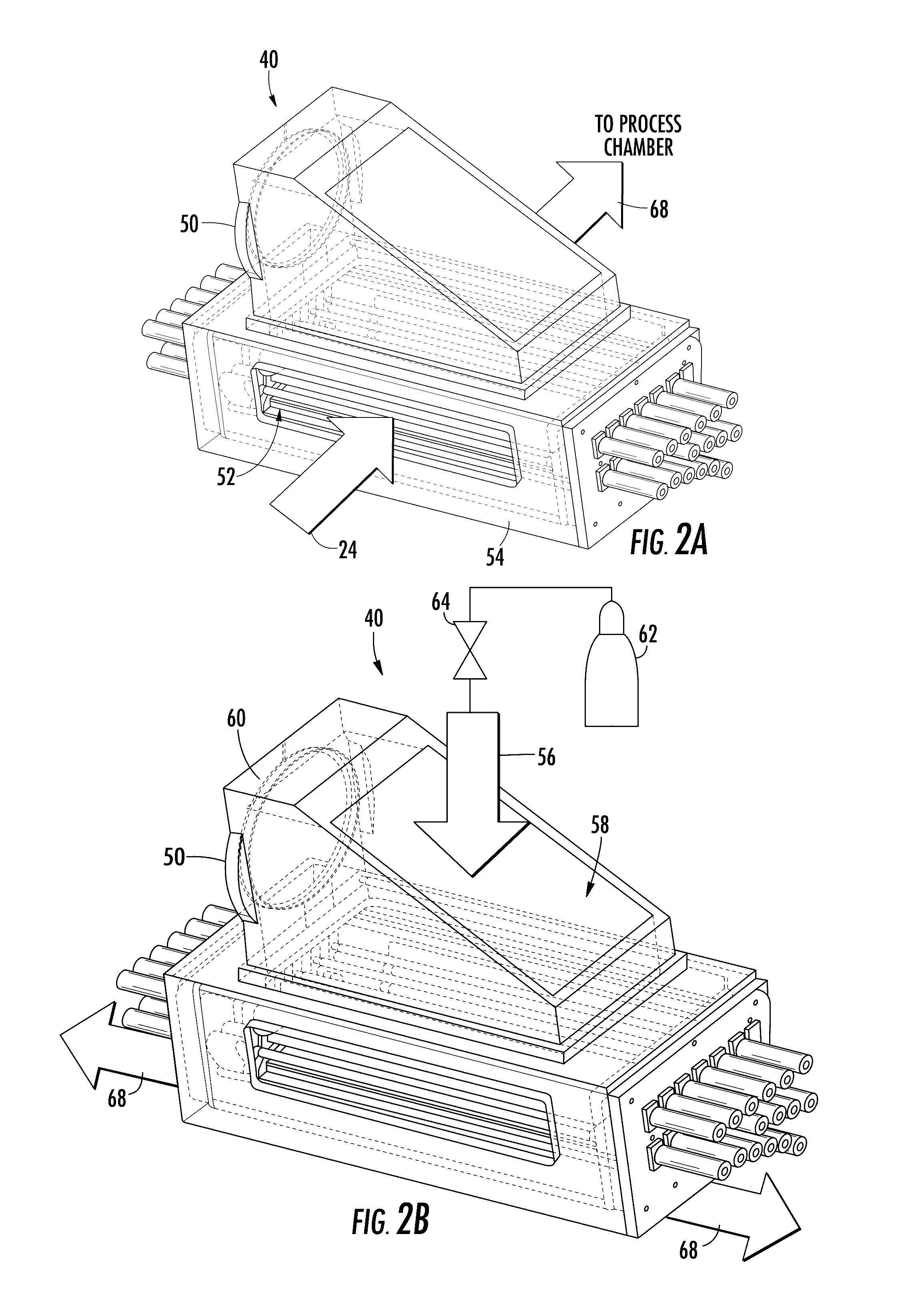
[0023]A system and method in accordance with the present disclosure will now be described more fully hereinafter with reference to the accompanying drawings, where embodiments of the system and method are shown. The system and method may be embodied in many different forms and are not be construed as being limited to the embodiments set forth herein. Instead, these embodiments are provided so this disclosure will be thorough and complete, and will fully convey the scope of the system and method to those skilled in the art.

[0024]For the sake of convenience and clarity, terms such as “top,”“bottom,”“upper,”“lower,”“vertical,”“horizontal,”“lateral,” and “longitudinal” will be used herein to describe the relative placement and orientation of these components and their constituent parts, each with respect to the geometry and orientation of a component of a semiconductor manufacturing device as appearing in the figures. The terminology will include the words specifically mentioned, deriva...


PUM

PropertyMeasurementUnit
Pressureaaaaaaaaaa
Compositionaaaaaaaaaa
Electrical conductoraaaaaaaaaa

Abstract

Provided herein are approaches for in-situ plasma cleaning of one or more components of an ion implantation system. In one approach, the component may include a beam-line component having one or more conductive beam optics. The system further includes a power supply for supplying a first voltage and first current to the component during a processing mode and a second voltage and second current to the component during a cleaning mode. The second voltage and current may be applied to the conductive beam optics of the component, in parallel, to selectively (e.g., individually) generate plasma around one or more of the one or more conductive beam optics. The system may further include a flow controller for adjusting an injection rate of an etchant gas supplied to the component, and a vacuum pump for adjusting pressure of an environment of the component.

Description

CROSS REFERENCE TO RELATED APPLICATION[0001]The present application is a non-provisional of U.S. Provisional Ser. No. 62 / 174,906, filed Jun. 12, 2015, the entire contents incorporated herein by reference.FIELD OF THE DISCLOSURE[0002]The disclosure relates generally to techniques for manufacturing electronic devices, and more particularly, to techniques for improving the performance and extending the lifetime of components within a processing chamber.BACKGROUND OF THE DISCLOSURE[0003]Ion implantation is a process of introducing dopants or impurities into a substrate via bombardment. In semiconductor manufacturing, the dopants are introduced to alter electrical, optical, or mechanical properties. For example, dopants may be introduced into an intrinsic semiconductor substrate to alter the type and level of conductivity of the substrate. In manufacturing an integrated circuit (IC), a precise doping profile provides improved IC performance. To achieve a desired doping profile, one or mo...

Claims


Application Information

Patent Timeline
IPC IPC(8): H01J37/317B08B7/00H01J37/34H01J37/24
CPCH01J37/3171H01J37/241H01J2237/335H01J37/3467H01J2237/334B08B7/0035H01J2237/057H01J2237/049H01J2237/022H01L21/67011H01J2237/047H01J2237/31705H01J37/32862H01J2237/04756C02F1/325
Inventor ANGLIN, KEVINLEE, WILLIAM DAVISKURUNCZI, PETERDOWNEY, RYANSCHEUER, JAY T.LIKHANSKII, ALEXANDREHOLBER, WILLIAM M.
Owner VARIAN SEMICON EQUIP ASSOC INC
Why Eureka
Eureka Blog
Learn More