Polyimide resin and metal-clad laminate comprising the same

a technology of polyimide resin and metal-clad laminate, which is applied in the field of polyimide resin, can solve the problems of affecting yield, complicated and time-consuming, and the thermoplastic polyimide layer has less dimensional stability and heat resistance, so as to avoid warpage, simplify the process, and save time and cos

Active Publication Date: 2016-12-22
ETERNAL MATERIALS CO LTD
View PDF3 Cites 10 Cited by
  • Summary
  • Abstract
  • Description
  • Claims
  • Application Information

AI Technical Summary

Benefits of technology

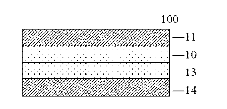
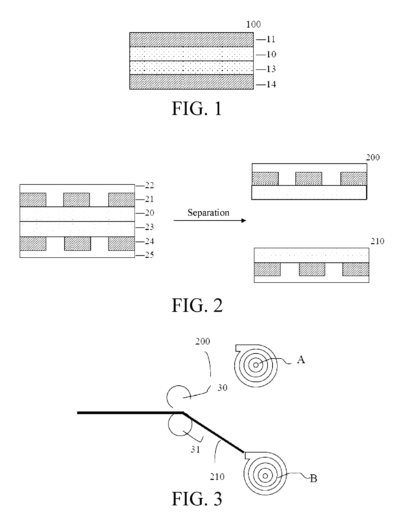
[0012]Through continuous research, the inventors have found a novel polyimide resin. The polyimide resin has at least two glass transition temperatures measured by dynamic mechanical analysis (DMA), can be directly applied to a metal substrate and provides proper peeling strength by adjusting the lamination temperature and pressure (i.e., generates adhesion upon hot pressing). The polyimide resin of the present disclosure is especially applicable to prepare a quasi double-sided two-layer metal clad laminate. The resulting quasi double-sided two-layer metal clad laminate can be easily separated into two single-sided flexible circuit boards after the fabrication of flexible printed circuits, and therefore, the present disclosure can effectively eliminate the disadvantages existing in the process for preparing a single-sided flexible circuit board from a single-sided copper clad laminate and avoid warpage. The present disclosure can use the equipment for preparing a double-sided metal foil printed circuit to prepare two single-sided flexible circuit boards at the same time, and therefore, results in the advantages of simplifying the process and saving time and cost. Besides, in addition to the quasi double-sided two-layer metal clad laminate, the present disclosure can also be used to prepare a double-sided two-layer metal clad laminate by adjusting the lamination temperature and pressure.

Problems solved by technology

The existing process involves several repetitions of coating and lamination, is complicated and takes a lot of time.
A thermoplastic polyimide layer has less dimensional stability and heat resistance, and so it is easy for foam and delamination to occur in the FCCL during a high temperature process, thereby affecting the yield.
However, since the adhesion between two polyimide layers is worse, a thermoplastic polyimide layer (TPI) is still required.
Thermoplastic polyimide has a lower glass transition temperature (Tg), less heat resistance, higher thermal expansion coefficient, greater size change during expansion and contraction, and is prone to cause warpage or delamination of the FCCL.
However, single-sided FCCLs tend to warp.
However, this increases the fabrication cost.

Method used


Image

  • Polyimide resin and metal-clad laminate comprising the same
  • Polyimide resin and metal-clad laminate comprising the same
  • Polyimide resin and metal-clad laminate comprising the same

Examples


example 1

[0109]58.84 g (0.2 mol) of 3,3′,4,4′-biphenyltetracarboxylic dianhydride (BPDA) and 43.62 g (0.2 mol) of pyromellitic dianhydride (PMDA) were dissolved in 2064 g of NMP. 2.32 g (0.02 mol) of 2-hydroxyethyl acrylate (HEA) was slowly added dropwise, and reacted for 2 hrs at 50° C. with stirring. Then, 20.02 g (0.1 mol) of 4,4′-oxydianiline (ODA), 24.85 g (0.1 mol) of PAN-H and 21.63 g (0.2 mol) of p-phenylene diamine (PPDA) were added to the solution, and reacted for 6 hrs at 50° C. with stirring after complete dissolution, to obtain a solution containing a first polymer precursor.

[0110]Then, 176.53 g (0.6 mol) of BPDA was added to the solution, stirred for 30 mins, followed by the addition of 64.89 g (0.6 mol) of PPDA, and then reacted for 6 hrs at 50° C. with stirring after complete dissolution, to form a second polymer precursor. The resulting formulation PAA-A1 contained the first polymer precursor and the second polymer precursor, and had a solids content of 20%. The first polyme...

example 2

[0112]58.84 g (0.2 mol) of BPDA and 43.62 g (0.2 mol) of PMDA were dissolved in 2059 g of NMP. 2.32 g (0.02 mol) of HEA was slowly added dropwise, and reacted for 2 hrs at 50° C. with stirring. Then, 24.03 g (0.12 mol) of ODA, 19.88 g (0.08 mol) of PAN-H and 21.63 g (0.2 mol) of PPDA were added to the solution, and reacted for 6 hrs at 50° C. with stirring after complete dissolution, to obtain a solution containing a first polymer precursor.

[0113]176.53 g (0.6 mol) of BPDA was added to the solution, stirred for 30 mins, followed by the addition of 64.89 g (0.6 mol) of PPDA, and then reacted for 6 hrs at 50° C. with stirring after complete dissolution, to form a second polymer precursor. The resulting formulation PAA-A2 contained the first polymer precursor and the second polymer precursor, and had a solids content of 20%. The first polymer precursor accounted for 40 mol % of the moles of the total polymer precursors.

[0114]Then, the process as describe in Example 1 was used to apply ...

example 3

[0115]58.84 g (0.2 mol) of BPDA and 43.62 g (0.2 mol) of PMDA were dissolved in 2054 g of NMP. 2.32 g (0.02 mol) of HEA was slowly added dropwise, and reacted for 2 hrs at 50° C. with stirring. Then, 28.03 g (0.14 mol) of ODA, 14.91 g (0.06 mol) of PAN-H and 21.63 g (0.2 mol) of PPDA were added to the solution, and reacted for 6 hrs at 50° C. with stirring after complete dissolution, to obtain a solution containing a first polymer precursor.

[0116]176.53 g (0.6 mol) of BPDA was added to the solution, stirred for 30 mins, followed by the addition of 64.89 g (0.6 mol) of PPDA, and then reacted for 6 hrs at 50° C. with stirring after complete dissolution, to form a second polymer precursor. The resulting formulation PAA-A3 contained the first polymer precursor and the second polymer precursor, and had a solids content of 20%. The first polymer precursor accounted for 40 mol % of the moles of the total polymer precursors.

[0117]Then, the process as describe in Example 1 was used to apply ...


PUM

PropertyMeasurementUnit
glass transition temperatureaaaaaaaaaa

Abstract

The present disclosure provides a polyimide resin having at least two glass transition temperatures measured by dynamic mechanical analysis (DMA). Also, a metal-clad laminate including the polyimide resin.

Description

CROSS REFERENCE TO THE RELATED APPLICATIONS[0001]This application claims the benefit of priority to Taiwan Patent Application Nos. 104119714 filed Jun. 17, 2015, 104140909 filed Dec. 4, 2015 and 105113634 filed Apr. 29, 2016, the contents of which are incorporated herein by reference in their entity.BACKGROUND OF THE INVENTION[0002]1. Technical Field[0003]The present disclosure relates to a polyimide resin. In particular, the present disclosure relates to a polyimide resin applicable to a metal clad laminate.[0004]2. Description of the Related Art[0005]A flexible printed circuit (FPC) board is made from the raw materials of a flexible insulation layer and copper foil which have the capacity to endure bending deformation. Due to its flexibility and bendability, FPC enables three-dimensional wiring through adaptation to the size and shape of the product and is light and thin, making it one of the essential components in various high-tech devices such as cameras, video cameras, display...

Claims


Application Information

Patent Timeline
Patent Type & Authority Applications(United States)
IPC IPC(8): C08G73/10H05K1/02H05K1/03C09D179/08
CPCC08G73/1042C08G73/1075C08G73/106H05K2201/0154C09D179/08H05K1/028H05K1/0353C08G73/1007B32B15/08B32B27/281B32B33/00B32B2250/42B32B2457/08H05K1/02B32B7/12B32B15/20B32B27/08B32B27/18B32B2250/40B32B2270/00C08G73/1082H05K3/0097H05K3/022H05K2203/0143H05K2203/1545C08G73/10C08G73/1078C08L79/08C08L2205/025
Inventor CHIANG, SHUN-JENWU, CHUNG-JENHUANG, PO-YUCHOU, MENG-YENHO, CHANG-HONGCHENG, CHUN-KAI
Owner ETERNAL MATERIALS CO LTD
Why Eureka
Try Eureka