Power generation system exhaust cooling

a technology for power generation systems and exhaust gas, applied in the field of power generation systems, can solve the problems of increasing the probability of scr catalyst damage due to excess temperature during various modes of gas turbine operation, increasing the operating cost of gas turbine power generation systems, and reducing the power provided to the power grid, so as to reduce the temperature of the exhaust gas stream

Active Publication Date: 2016-12-29
GENERAL ELECTRIC CO
View PDF0 Cites 21 Cited by
  • Summary
  • Abstract
  • Description
  • Claims
  • Application Information

AI Technical Summary

Benefits of technology

[0010]A first aspect of the disclosure provides an airflow control system for a gas turbine system, including: an airflow generation system for attachment to a rotatable expander shaft of a gas turbine system, downstream of the gas turbine system, for drawing in a flow of ambient air thro

Problems solved by technology

Because of the possibility of catalyst damage due to a failure of an external blower system, a redundant external blower system is typically utilized.
These external blower systems include many components, such as blowers, motors, filters, air intake structures, and large ducts, which are expensive, bulky, and add to the operating cost of a gas turbine power generation system.
Additionally the exter

Method used


Image

  • Power generation system exhaust cooling
  • Power generation system exhaust cooling
  • Power generation system exhaust cooling

Examples


Embodiment Construction

[0021]As indicated above, the disclosure relates generally to power generation systems, and more particularly, to systems and methods for cooling the exhaust gas of power generation systems.

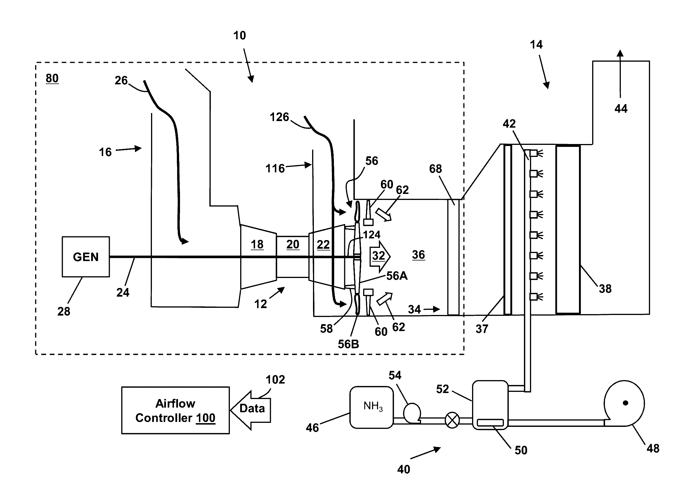
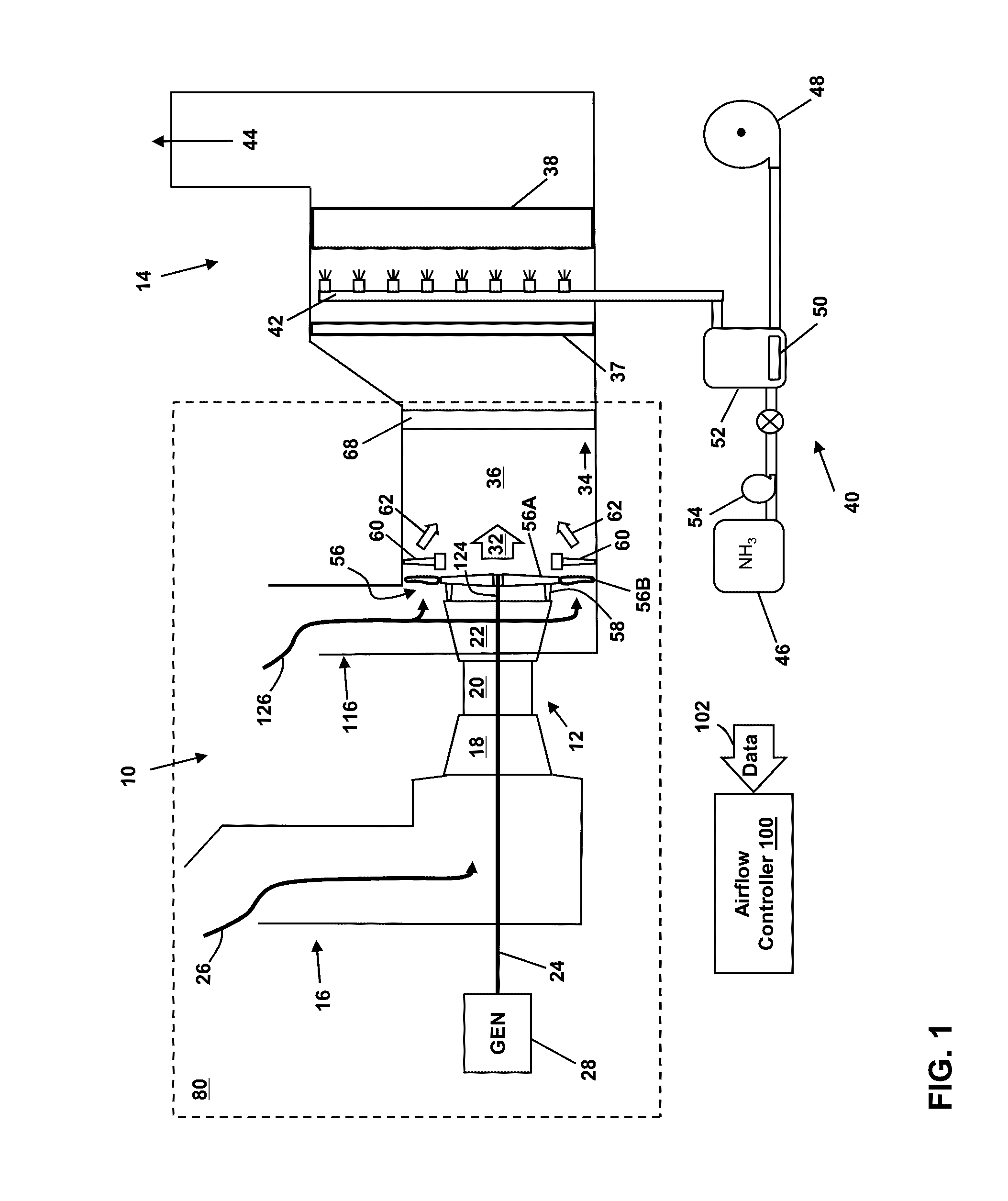
[0022]FIG. 1 is a block diagram of a turbomachine system (e.g., a simple cycle gas turbine power generation system 10) that includes a gas turbine system 12 and an exhaust processing system 14. The gas turbine system 12 may combust liquid or gas fuel, such as natural gas and / or a hydrogen-rich synthetic gas, to generate hot combustion gases to drive the gas turbine system 12.

[0023]The gas turbine system 12 includes an air intake section 16, a compressor component 18, a combustor component 20, and a turbine component 22. The turbine component22 is drivingly coupled to the compressor component 18 via a shaft 24. In operation, air (e.g., ambient air) enters the gas turbine system 12 through the air intake section 16 (indicated by arrow 26) and is pressurized in the compressor component 18. The compr...


PUM


Abstract

A power generation system according to an embodiment includes: a gas turbine system including a compressor component, a combustor component, and a turbine component; an airflow generation system coupled to an expander shaft downstream of the gas turbine system for drawing in a flow of ambient air through an air intake section; a mixing area for receiving an exhaust gas stream produced by the gas turbine system;
    • a flow directing system for directing the flow of ambient air generated by the airflow generation system to the mixing area to reduce a temperature of the exhaust gas stream;
    • and an exhaust processing system for processing the reduced temperature exhaust gas stream.

Description

CROSS-REFERENCE TO RELATED APPLICATIONS[0001]This application is related to co-pending U.S. application Ser. Nos. ______, GE docket numbers 280650-1, 280685-1, 280687-1, 280688-1, 280692-1, 280707-1, 280714-1, 280731-1, 280815-1, 281003-1, 281004-1, 281005-1 and 281007-1 all filed on ______.BACKGROUND OF THE INVENTION[0002]The disclosure relates generally to power generation systems, and more particularly, to systems and methods for cooling the exhaust gas of power generation systems.[0003]Exhaust gas from power generation systems, for example a simple cycle gas turbine power generation system, often must meet stringent regulatory requirements for the composition of the exhaust gas released into the atmosphere. One of the components typically found in the exhaust gas of a gas turbine power generation system and subject to regulation is nitrogen oxide (i.e., NOR), which includes, for example, nitric oxide and nitrogen dioxide. To remove the NOx from the exhaust gas stream, technology...

Claims


Application Information

Patent Timeline
IPC IPC(8): F01N3/05F02C3/10F01N3/20
CPCF01N3/05F01N3/2066F05D2220/36F01N2270/02F02C3/10F02C6/00F02C6/10F02C7/141F02C9/16F01D25/305Y02E20/14Y02E20/16
Inventor KULKARNI, PARAG PRAKASHDAVIS, JR., LEWIS BERKLEYREED, ROBERT JOSEPH
Owner GENERAL ELECTRIC CO
Why Eureka
Try Eureka