Method and means to improve the effects of electrical cell and neuron stimulation with random stimulation in both location and time

a random stimulation and electrical cell technology, applied in the field of cellular electrical stimulation, can solve the problems of not finding a solution for this problem, unable to offer adjustment on the stimulation site, and difficulty for neurosurgeons to place the stimulating electrode in the correct pla

Active Publication Date: 2017-01-12
MONTEIRO SERGIO LARA PEREIRA
View PDF3 Cites 9 Cited by
  • Summary
  • Abstract
  • Description
  • Claims
  • Application Information

AI Technical Summary

Benefits of technology

[0013]Another of the advantages of this invention is to adjust the position of the brain stimulation to the best place to cause optimal results for the patient.

Problems solved by technology

Some of the failures are due to side effects, which may well be a consequence of incorrectly placed stimulators, as acknowledged by many neurosurgeons, including in this case stimulators placed other than the exact center of the target area.
Indeed, it is very difficult for the neurosurgeon to place the stimulating electrode in the correct place, deep inside the brain and not even open to visual inspection.
Unfortunately, the picafina must be of small size in order to minimize injure to the brain tissue, which in turn precludes many wirings running through it, this being one of the reasons for the current devices having so few stimulating pads (or rings, or electrodes) which offer so few options for the origin of the stimulating pulses.
Indeed, many neurosurgeons would like to have more options, more electrical pads to choose as initiation points for the electrical stimulation, but a solution for this problem was never found.
It is worth to point out that the prior art for DBS at the present moment is capable of initiate an electrical stimulation from any of the four rings, therefore offering a small (1 mm.) adjustment on the stimulation site, but it is not capable of offering adjustment on the stimulation site from the position where one of the ring is to another site where the insulator spacer is.
A similar problem is encountered by heart pacemakers.
Old art has the disadvantage that the electrical pulse is injected over the whole, or at least most of the volume of the attachment.
This has the disadvantage that the pulse is injected over too large an area into the heart muscle to be able to control its propagation time, which is needed for a proper, sequential contraction of the heart muscle, needed for optimal pumping.
If the electrical pulse is not injected correctly, then the heart pumping is not sequentially squeezing the blood forward, as needed, causing a non-optimal pumping.
Yet, such symmetrical delivery is not desirable, because the normal, natural electrical pulse is known to travel through the heart along certain paths with specific speeds and delay times, starting from the sinus, these speeds and delays being a function of the electrical characteristics of the heart muscle, known in electrical engineering as resistance, capacitance, inductance, etc.
Normally the pulse initiates from a nerve that delivers it on the coronary sinus, and from there the electrical pulse propagates with speeds that depend on the tissue properties along each direction, which is a much studied problem.
This point of delivery is a problem that has not yet been solved, in spite of it being a known source of problems with the pacemaking pulse.
Indeed, if the electrical pulse from the pacemaker is delivered in the wrong place then the heart will not beat correctly, because the contraction, which must happen in a particular sequence will not be correct.
Ideally the heart surgeon would be able to precisely control the depth on the heart wall and direction of delivery of the electrical pulse, as opposed of the voltage only, which is the only controllable value in current art, which also delivers the pulse on all directions, which is not ideal either.
It is also possible to advance or retreat by less than 100%, but in this case not all points would be covered; it would be an improvement on the current art but not as complete an improvement as possible to make.

Method used


Image

  • Method and means to improve the effects of electrical cell and neuron stimulation with random stimulation in both location and time
  • Method and means to improve the effects of electrical cell and neuron stimulation with random stimulation in both location and time
  • Method and means to improve the effects of electrical cell and neuron stimulation with random stimulation in both location and time

Examples


embodiment

Preferred Embodiment

FIG. 13

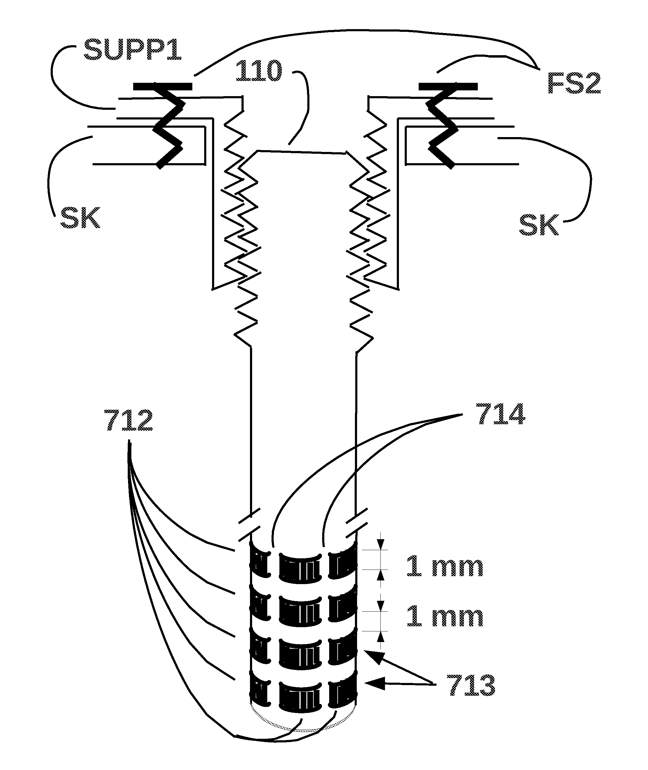
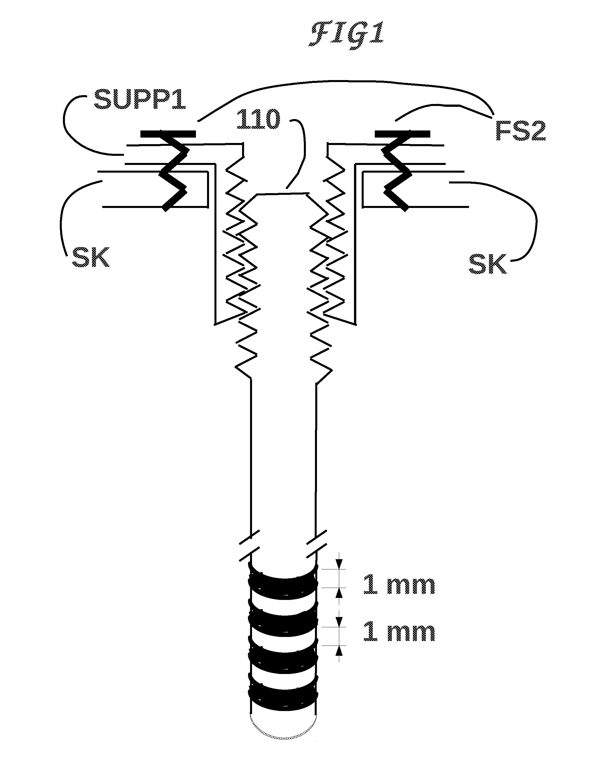
[0053]We will describe a main embodiment of our invention for use in DBS (Deep Brain Stimulation). Variations for use in more superficial areas of the brain, or for use in spinal cord, or for use as TENS devices (Transcutaneous Electrical Nerve Stimulation, pain control), or for use as heart pacemakers, etc. will be apparent to the ones skilled in the relevant arts.

[0054]We firstly make a shorter description intended for engineers and technicians, then a longer description for the layperson, or a person who is familiar with some of the aspects of the invention but not familiar with all of its aspects. Note that the invention involves more than one field of expertise, so the number of people familiar with all its aspects is small, which decreases the possible pool for the famous person “skilled in the art” well known to the patent offices worldwide. To compensate for this shrunk “skilled” pool we try to describe our invention with more details and from seve...


PUM


Abstract

An electric stimulator for brain, heart, skin and internal organs in animals and plants where the electrodes are distributed on a supporting structure. The supporting structure may be adapted for brain, heart, skin or other internal organs, as for DBS, heart pacemaker, TENS, etc. The invention discloses a plurality of electrodes at the surface of the supporting structure, from which electrically stimulating currents can be injected into the organism. Turning off an electrode while turning on another electrode has the effect of moving the stimulation within the body of the organism from one point to another point, with the same effect but with less spent energy than physically moving the whole electrode support. We call this electrode shifting. Rotational and translational electrode shifting are possible. The invention also discloses random changes of the electrode shifting, and random changes of the stimulation time and of the stimulation duration.

Description

CROSS-REFERENCE TO RELATED APPLICATIONS[0001]This application is a continuation in part of U.S. patent application Ser. No. 14 / 741,136, filing date 2015 Jun. 16, title “Method and means to adjust the positioning of stimulating neural and muscular electrode”, now abandoned, which is a continuation of U.S. patent application Ser. No. 14 / 150,767, filing date 2014 Jan. 9, title “Device and means for adjusting the position of DBS brain and other neural and muscular implants”, publication number US 2014-0222018 A1, publication date 2014 Aug. 7, now U.S. Pat. No. 9,089,687, issued on 2015 Jul. 28, which is a continuation of U.S. patent application Ser. No. 13 / 117,132, filing date 2011 May 26, title “Method and means to adjust the positioning of stimulating neural and muscular electrode, published US-2012-0029590 A1 on 2012 Feb. 2, now U.S. Pat. No. 8,670,837, issued on 2014 Mar. 11.[0002]This application claims priority to U.S. PPA application No. 61 / 396,334, filing date 2010 May 26 “Metho...

Claims


Application Information

Patent Timeline
Patent Type & Authority Applications(United States)
IPC IPC(8): A61N1/08A61N1/36A61N1/02A61N1/05A61N1/04
CPCA61N1/08A61N1/0529A61N1/0587A61N1/0551A61N1/36103A61N1/025A61N1/36014A61N1/36071A61N1/3606A61N1/0456A61N1/0534A61N1/0539A61N1/057A61N1/36034A61N1/36182A61N1/36185A61N1/3684A61N1/3686A61N1/37512A61N1/37518A61B34/70
Inventor MONTEIRO, SERGIO LARA PEREIRA
Owner MONTEIRO SERGIO LARA PEREIRA
Why Eureka
Try Eureka