
Dual catalyst heating system

a heating system and catalyst technology, applied in the direction of machines/engines, separation processes, electric control, etc., can solve the problems of low conversion efficiency of scr catalyst, temperature-dependent scr reaction, and inability to work at low temperatures, so as to reduce the nitrogen oxide content of exhaust gas

Active Publication Date: 2017-02-09
FORD GLOBAL TECH LLC
View PDF13 Cites 23 Cited by
  • Summary
  • Abstract
  • Description
  • Claims
  • Application Information

AI Technical Summary

Benefits of technology

The patent describes a method that has the same benefits as a system. The technical effect of the method is the same as the system, which means that it can achieve the same results as the system.

Problems solved by technology

However, the inventors herein have recognized potential issues with such approaches to the aftertreatment of diesel gases.
For example, the thermolytic-hydrolytic conversion of the urea-containing reducing agent does not work at low temperatures.
Further, the SCR reaction is also temperature-dependent.
Under conditions with low exhaust gas temperatures, e.g., in urban traffic, conversion efficiency in the SCR catalyst is relatively low.
Even when the temperature of exhaust gas released from the engine is high, due to the position of the SCR catalyst downstream of one or more other exhaust catalysts (e.g., as the second or third element in an exhaust tract), thermal energy of exhaust gas may be lost between the combustion engine and the SCR catalyst.
As a result, the exhaust reaching the SCR catalyst may not be hot enough.
In addition, rear-injection of a urea solution onto a warm surface, such as a rear face of the first catalyst, as opposed to injection further downstream at lower temperatures, increases decomposition of exhaust gas emissions.

Method used


Image

  • Dual catalyst heating system
  • Dual catalyst heating system
  • Dual catalyst heating system

Examples


second embodiment

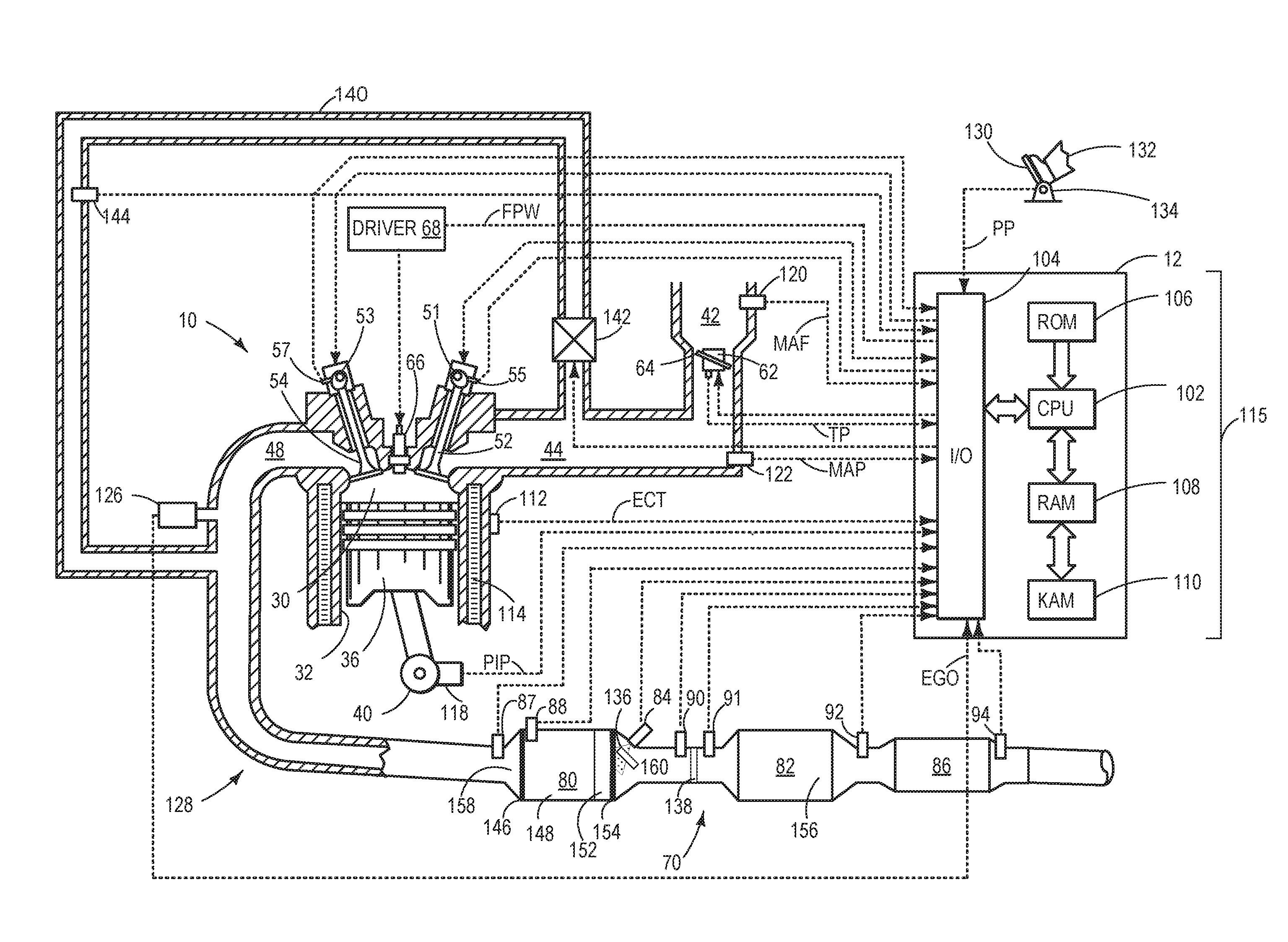
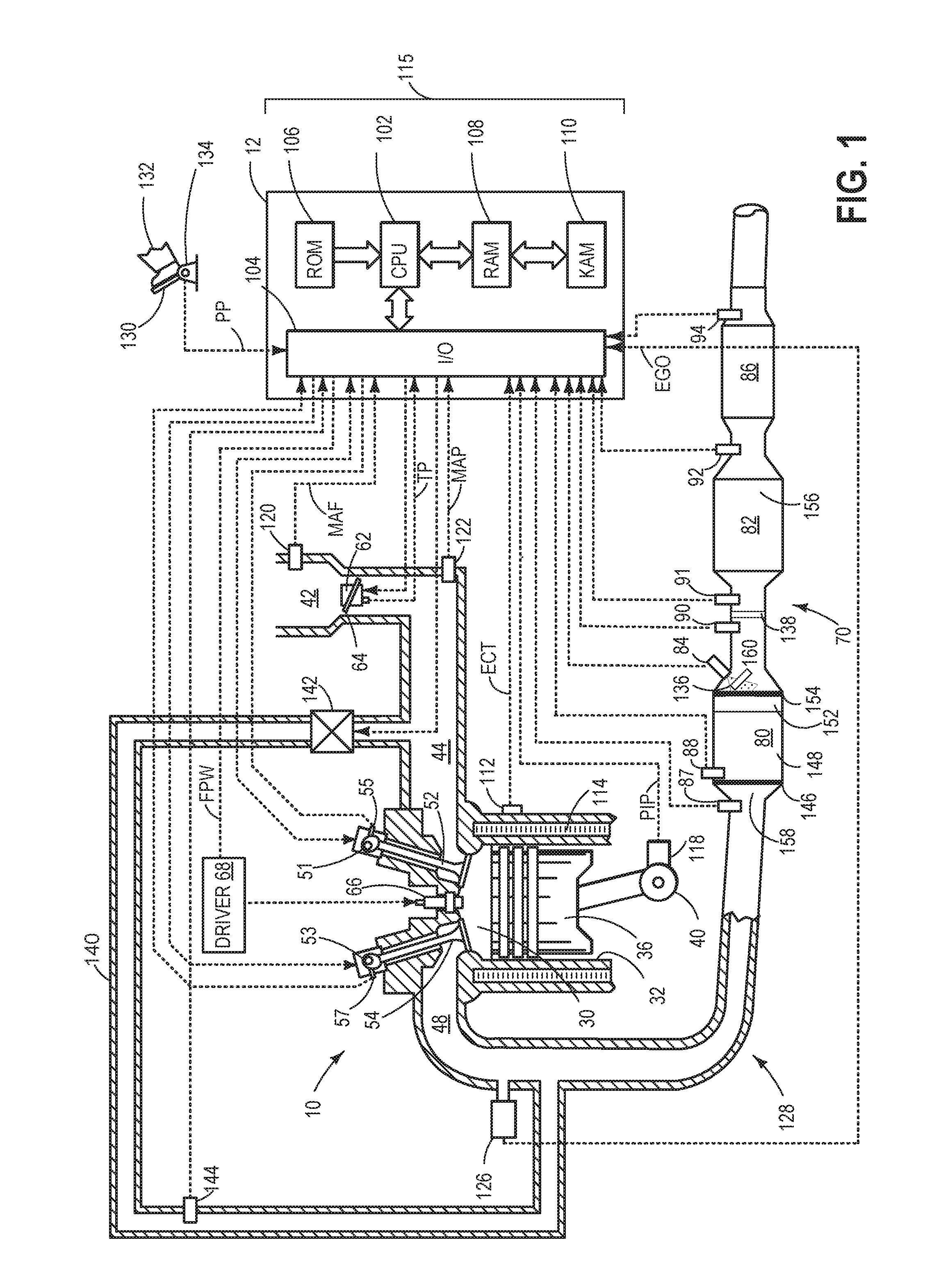
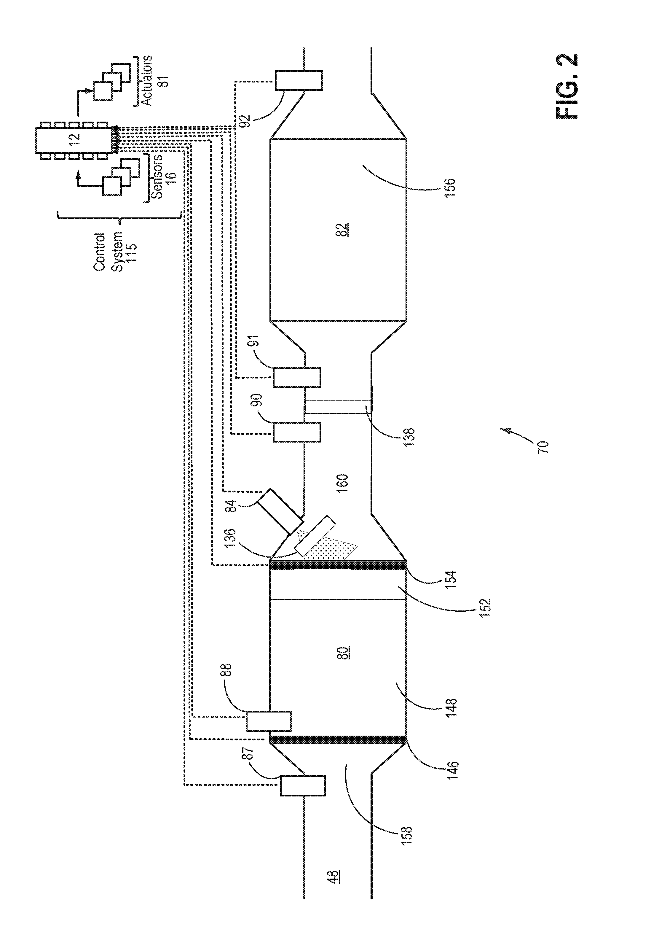
[0088]In a second embodiment, a method comprises an exhaust gas aftertreatment including following an engine start, switching on a first heat device coupled to an inlet of a first catalyst, the first catalyst arranged upstream of a second catalyst in an exhaust passage; and when an exhaust temperature reaches a first temperature threshold value, introducing, via a feed device, a reducing agent into the exhaust passage between the first and second catalyst; and switching on a second heat device coupled to an outlet of the first catalyst. In a first example of the method, the method further comprises wherein when the exhaust temperature reaches a second temperature threshold value, switching off the second heat device and continuing introduction of the reducing agent, wherein the second temperature threshold value is higher than the first temperature threshold value. A second example of the method optionally includes the first example, and further includes wherein the first heat devic...

third embodiment

[0089]In a third embodiment, a method comprises an engine exhaust including responsive to an engine cold-start condition, actuating a first heater coupled to an inlet of a first exhaust oxidation catalyst to raise an exhaust temperature, the first catalyst arranged upstream of a second selective reduction catalyst; and responsive to the exhaust temperature exceeding a first threshold, actuating a second heater coupled to an outlet of the first exhaust oxidation catalyst while injecting an amount of reducing agent, rearwards, onto the outlet of the first catalyst, a direction of the injecting opposite to the direction of exhaust flow. In a first example of the method, the method further comprises wherein while actuating the second heater, disabling the first heater. A second example of the method optionally includes the first example, and further includes wherein responsive to the exhaust temperature exceeding a second threshold, higher than the first threshold, disabling at least th...


PUM

PropertyMeasurementUnit
temperatureaaaaaaaaaa
temperature thresholdaaaaaaaaaa

Abstract

Methods and systems are provided for an exhaust gas aftertreatment system for a combustion engine in a motor vehicle. In one example, the exhaust gas aftertreatment comprises at least two catalyst devices arranged in an exhaust tract, and a feed device for a reducing agent arranged between the two catalysts, and which furthermore comprises a first heat device at the inlet of the first catalyst and a second heat device downstream thereof, the system adapted for the reduction of nitrogen oxides.

Description

CROSS-REFERENCE TO RELATED APPLICATION[0001]This application claims priority to German Patent Application No. 102015214906.4, filed Aug. 5, 2015, the entire contents of which are hereby incorporated by reference for all purposes.FIELD[0002]The present invention relates to a system for exhaust gas aftertreatment of a combustion engine in a motor vehicle, having at least two catalyst devices arranged in the exhaust tract, and at least two heating devices, in particular for reducing nitrogen oxides via a reducing agent introduced into the exhaust gas flow.BACKGROUND AND SUMMARY[0003]Aftertreatment of diesel exhaust gases is used inter alia to reduce the nitrogen oxide content of exhaust gas. One known method for this purpose is “selective catalytic reduction” (SCR). In SCR, nitrogen oxides are reduced to water and nitrogen over a catalyst by the reducing agent ammonia. Conventionally, the ammonia is introduced in the form of a urea solution (e.g., AdBlue) into the exhaust tract ahead o...

Claims


Application Information

Patent Timeline
Patent Type & Authority Applications(United States)
IPC IPC(8): F02D41/02F01N9/00B01D53/94F01N3/20F01N3/28F01N11/00F02D41/26F01N3/08
CPCF02D41/024B01D2255/20723F01N9/00F01N3/0842F01N3/2066F01N3/2892F01N3/2006F01N11/002B01D53/9418F01N2250/12F01N2510/06F01N2560/06F01N2570/14F01N2900/08F01N2900/1404B01D2255/91B01D2255/808B01D2255/20761B01D2255/50F02D41/26F01N13/0093F01N3/28F01N2610/102F01N2900/1602B01D53/9477B01D2255/20738B01D2258/012Y02A50/20Y02T10/12Y02T10/40
Inventor BALENOVIC, MARIOGOEBEL, FELIXSCHNEIDER, MATTHEW ALLENREICHERT, MARTINADE SMET, FREDERIKROSS, PETER
Owner FORD GLOBAL TECH LLC
Learn More