
NOx TRAP

a nox trap and substrate technology, applied in the direction of metal/metal-oxide/metal-hydroxide catalysts, physical/chemical process catalysts, separation processes, etc., can solve the problems of not being believed, the improvement made involved, and the difficulty of nox trap substrates presenting greater difficulties than gasoline-fuelled engines, etc., to achieve the effect of improving heat generation efficiency, reducing the number of nox traps, and slow temperature propagation through the length of nox trap

Inactive Publication Date: 2017-02-16
JOHNSON MATTHEY PLC
View PDF1 Cites 15 Cited by
  • Summary
  • Abstract
  • Description
  • Claims
  • Application Information

AI Technical Summary

Benefits of technology

The inventors have observed that the temperature in a NOx trap substrate is slow to spread, so they aim to improve heat generation in the downstream part of the NOx trap to help release trapped sulphur more efficiently and with less desulphation effort. The invention aims to create an improved NOx trap that can better manage trapped sulphur.

Problems solved by technology

Compression ignition engines operate with lean fuel / air ratios, and give good fuel economy, but present greater difficulties than gasoline-fuelled engines in NOx storage and conversion, because of the resulting lean exhaust gases.
Gasoline-fuelled engines are generally operated closer to λ=1, and although NOx conversion presents slightly fewer difficulties than with Diesel, sulphur accumulation on, and release from, NOx traps may present some difficulties.
However, it is not believed that any such improvement made has involved changing the structure of the NOx trap itself.
In practical terms, therefore, accumulated sulphur is moved through the trap, and there is a tendency for the rear of the trap not to be fully desulphated.

Method used


Image

  • NOx TRAP
  • NOx TRAP
  • NOx TRAP

Examples


example 1

Lean NOx Trap Formulation

[0035]A 400 cells per square inch flow-through cordierite substrate monolith was coated with a two layer NOx trap formulation comprising a first, lower layer comprising 2 gin−3 alumina, 2 gin−3 particulate ceria, 90 gft−3 Pt, 25 gft−3 Pd and 800 gft−3 Ba and a second layer comprising 0.5 gin−3 85 wt % zirconia doped with rare earth elements, 10 gft−3 Rh and 400 gft−3 ceria sol. The first layer was coated on the virgin substrate monolith using the method disclosed in WO 99 / 47260 followed by drying for 30 minutes in a forced air drier at 100° C. and then by firing at 500° C. for 2 hours before the second layer was applied and the same drying a firing procedure was repeated. This NOx trap was labelled LNT1.

[0036]LNT2 was prepared using an identical procedure except in that 400 gft−3 ceria sol was also added to the lower layer formulation.

example 2

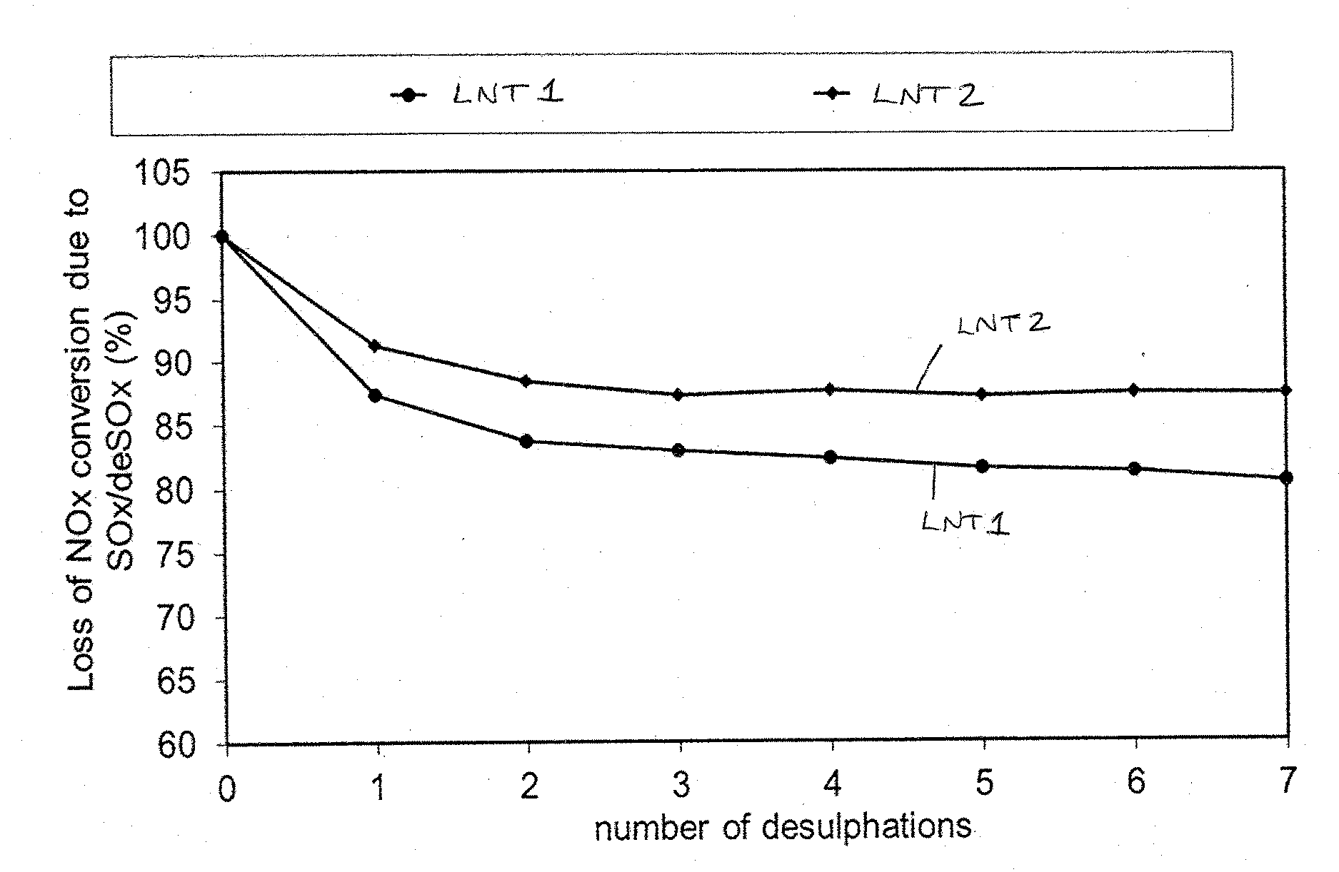
Synthetic Catalytic Activity Test (SCAT) Repeat SOx / deSOx Test

[0037]A core was cut from each of LNT1 and LNT2 and each core was tested in turn using on a Synthetic Catalytic Activity Test (SCAT) apparatus using the following conditions:

[0038]1) Cycle between 300 seconds lean / 20 seconds rich at an inlet temperature of 350° C.[0039]5 cycles with no sulphur to evaluate clean NOx performance; and[0040]5 cycles with sulphur to sulphate sample to 2 g / litre

[0041]2) Desulphate at 500° C. for 5 minutes[0042]Cycle between 50 seconds rich / 10 seconds lean

[0043]3) 300 seconds lean / 20 seconds rich at 350° C.[0044]5 cycles with no sulfur to evaluate desulfated NOx performance; and[0045]5 cycles with sulfur to sulfate to 2 g / l

[0046]4) Repeat

[0047]The gas conditions used are set out in Table 1.

TABLE 1LeanRichLeanRichdesulphationdesulphationLength (secs)300201050NO (ppm)100200——CO (%)0.03212CO2 (%)610610C3H6 (ppm)501700501700H2 (%)00.400.4O2 (%)111.561.5H2O (%)12126.612Flow rate47394739(l / min)

[0048]T...

example 3

NOx Trap Lower Layer CO Oxidation Activity

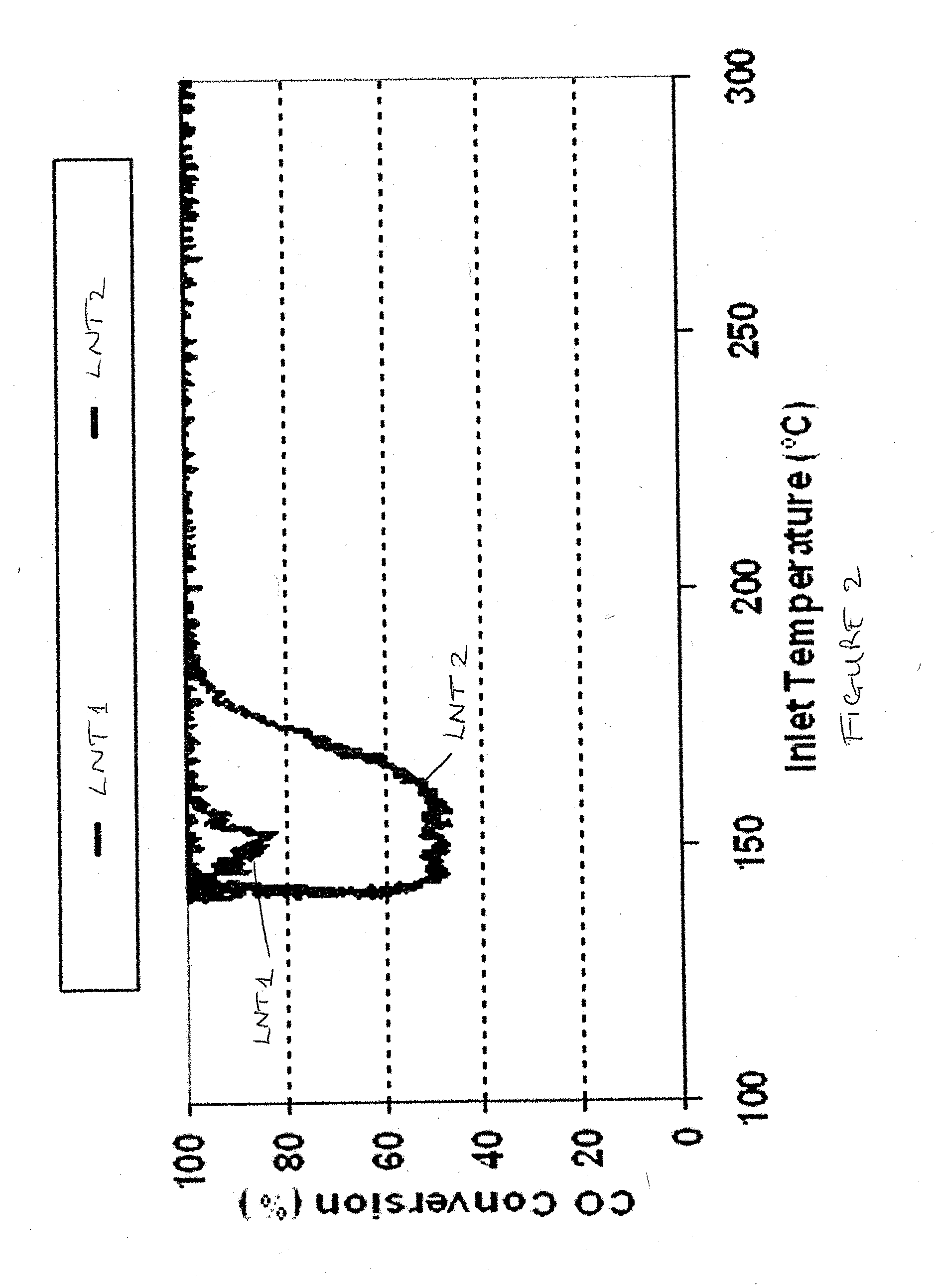
[0049]Substrate monoliths coated with the lower layers only of LNT1 and LNT2 following drying and firing prepared as described in Example 1 were aged at 800° C. for 5 hours in 10% H2O, 10% O2, balance N2. The substrate monoliths were each tested on a laboratory bench-mounted 1.9 litre Euro 4 Diesel engine by removing an existing NOx trap and replacing it with the LNT1 (lower layer) or LNT2 (lower layer) substrate monoliths.

[0050]An engine speed of 1200 rpm was selected and the engine torque was varied to achieve a desired catalyst inlet temperature. The evaluation started with a catalyst inlet temperature of 350° C. The engine torque was adjusted to ramp the inlet temperature down to <150° C., sufficient to achieve carbon monoxide oxidation “light-out”. In practice this was done by reducing the engine torque from 100 Nm to 5 Nm over 10 minutes. Following “light-out”, the engine torque was ramped back up at a rate of approximately 7° C. / min t...


PUM

PropertyMeasurementUnit
temperatureaaaaaaaaaa
diameteraaaaaaaaaa
inlet temperatureaaaaaaaaaa

Abstract

A NOx trap comprises components comprising at least one platinum group metal, at least one NOx storage material and bulk ceria or a bulk cerium-containing mixed oxide deposited uniformly in a first layer on a honeycombed substrate monolith, the components in the first layer having a first, upstream, zone having increased activity relative to a second, downstream zone for oxidising hydrocarbons and carbon monoxide, and a second, downstream, zone having increased activity to generate heat during a desulphation event, relative to the first zone, wherein the second zone comprises a dispersion of rare earth oxide, wherein the rare earth oxide loading in the second zone is greater than the loading in the first zone. An exhaust system for a lean burn internal combustion engine, a vehicle comprising a lean burn internal combustion engine and the exhaust system and methods of making the NOx trap are also disclosed.

Description

CROSS-REFERENCE TO RELATED APPLICATIONS[0001]This application is continuation of U.S. patent application Ser. No. 12 / 974,528, filed Dec. 21, 2010, and claims priority to British Patent Application No. 0922195.3, filed Dec. 21, 2009, the disclosures of which are incorporated herein by reference in their entirety for all purposes.FIELD OF THE INVENTION[0002]The present invention concerns improvements in NOx traps forming part of an internal combustion exhaust gas aftertreatment system, and more especially concerns NOx traps having an improved ability to be regenerated in respect of stored sulphur.BACKGROUND OF THE INVENTION[0003]The use of in-line NOx storage units, often called Lean NOx Traps but now more commonly called NOx traps or NOx Absorber Catalysts (NAC), is now well known in exhaust gas aftertreatment systems for lean burn internal combustion engines. Possibly the earliest patent publication is Toyota's EP 0 560 991, which describes how a NOx storage unit may be constructed ...

Claims


Application Information

Patent Timeline
Patent Type & Authority Applications(United States)
IPC IPC(8): B01J23/58B01J23/46B01J23/10F01N3/28B01J35/04B01J37/02F01N3/08B01D53/94B01J35/00
CPCB01J23/58B01D2255/20715B01D53/9422B01D53/9472B01J23/464B01J23/10B01J35/0006B01J35/04B01J37/0244F01N3/0842F01N3/0814F01N3/2828B01D2255/91B01D2255/908B01D2255/1021B01D2255/1023B01D2255/9032B01D2255/1025B01D2255/2042B01D2255/2092B01D2255/2065B01D53/9454B01D2255/202B01D2255/204B01D2255/2063B01D2255/2066B01D2255/2068B01D2255/407B01D2255/9022B01D2258/012B01J23/63B01J37/0242F01N3/0807F01N2510/0682Y02T10/12B01J35/19B01D53/60F01N3/0885B01J35/56
Inventor CHANDLER, GUY RICHARDMOUNTSTEVENS, ELIZABETH HAZELPHILLIPS, PAUL RICHARDSWALLOW, DANIEL
Owner JOHNSON MATTHEY PLC
Learn More