Method and apparatus for extracting electrical energy from photovoltaic module
a photovoltaic module and electrical energy technology, applied in the energy field, can solve the problems of photovoltaic cells, limiting the wide development of plants converting solar radiation, instantaneous and irrevocable energy loss, lack of compensation, etc., and achieve the effect of improving the efficiency of the system pv module and reducing electrical energy loss
- Summary
- Abstract
- Description
- Claims
- Application Information
AI Technical Summary
Benefits of technology
Problems solved by technology
Method used
Image
Examples
example 1
[0077]Experimental verification of the identity of both channels on the registration of energy amount was carried out at different levels of insolation. Level of average insolation was assessed by normalizing the average power obtained through channel 1 for a specified exposition to rated power of PV module. Exposures time was chosen arbitrarily, but not less than 60 seconds. Test results are given in Table 7 of this description. To check the proposed method for take-off electrical energy, the EETOS apparatus was included in channel 2 and tested similarly to channel 1. The results of this testing are given in Table 7. Channel 2 with the included EETOS apparatus, that is the subject of the invention, showed better performance at all levels of insolation. The effectiveness of the EETOS apparatus increases with decreasing insolation level from 103.2% if the insolation level is 91.2% to 3309% if the insolation level is 0.1% of the rated power of PV module.
TABLE 7The average power receiv...
example 2
[0078]Experimental verification of the effectiveness of the proposed method for take-off electrical energy was performed by monitoring the work of both channels around the daylight hours. Evaluation of the average insolation throughout the daylight hours was performed by normalizing the amount of energy from channel 1 to the maximum amount of energy received per daylight hours in channel 1 during the entire period of observation. Channel 2 operated either with included EETOS apparatus (09 / 24 and 09 / 25) or without it. The test results are given in Table 8. The proposed method has allowed to increase the amount of energy received per daylight hours by 27.8% and 22.9% at an average insolation of 80.1% and 88.5% respectively.
TABLE 8The Total Energy received from the PV modules with nominal power of 190 W atcondition of EETOS system application (Comparative Table)Channel 1 and Channel 2 are equallyloaded under the same insolationDate (day andInsolationChannel 1Channel 2Ratiomonth)level, ...
example 3
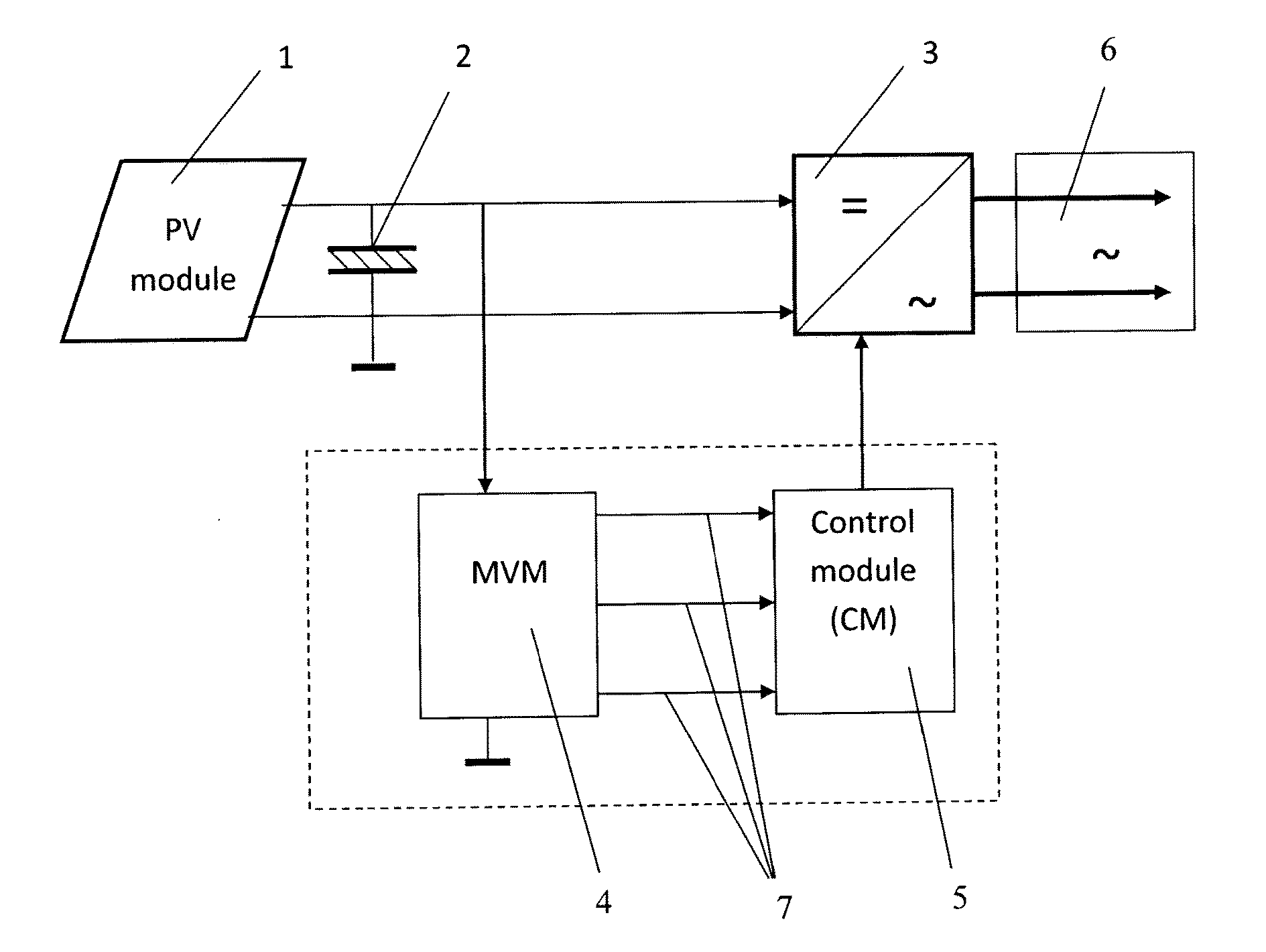
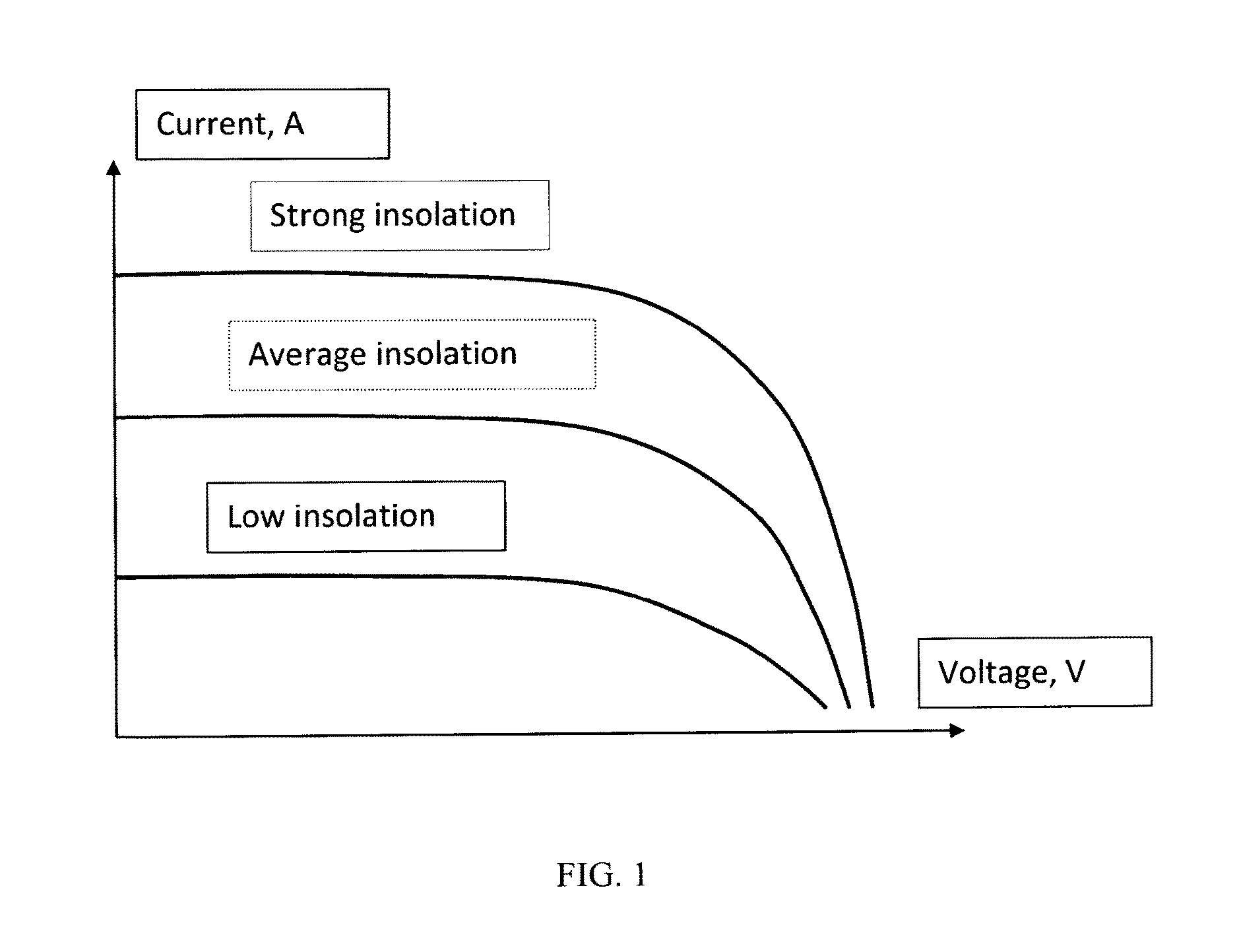
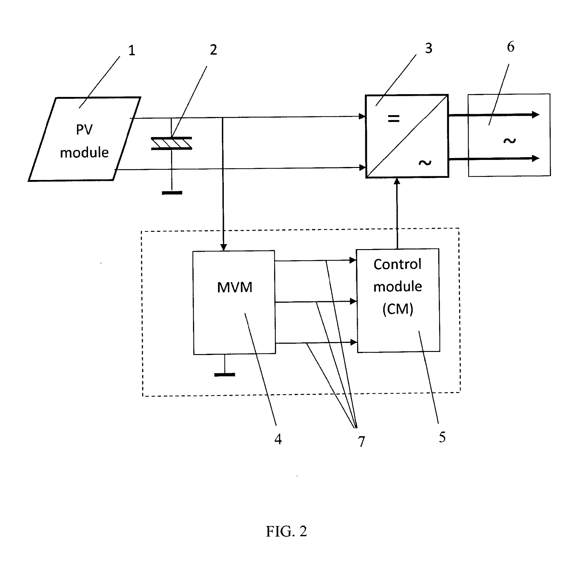
[0079]PV module made on the base of monocrystalline silicon cells was used for experimental verification of feasibility of the proposed apparatus. In accordance with the specification PV module has the following parameters: rated power—190 W, open circuit voltage Uoc=43.4 V, short-circuit current—6.5 A, internal resistance—6.3 Ohm, the calculated MPP voltage Umpp=0.8·Uoc=34.7 V. For PV module based on monocrystalline silicon cells a dependence of MPP on the insolation level is typical and close to the type 2 (FIG. 6). In this case, the method for take-off electrical energy was realized by adjusting system to three voltage levels using three voltage threshold sensors (4) and inverter with three power levels (3). Capacitor (2) consists of 7 modules BSC 6-30 based on structurally perfect carbon forms and aqueous electrolyte. In accordance with the BSC 6-30 specification it has: electrical capacity—30 F, internal resistance—less as 0.15 Ohm, and the optimal current—10 A. In this case, e...
PUM
 Abstract
Description
Claims
Application Information
 - R&D
- Intellectual Property
- Life Sciences
- Materials
- Tech Scout
- Unparalleled Data Quality
- Higher Quality Content
- 60% Fewer Hallucinations
Browse by: Latest US Patents, China's latest patents, Technical Efficacy Thesaurus, Application Domain, Technology Topic, Popular Technical Reports.
© 2025 PatSnap. All rights reserved.Legal|Privacy policy|Modern Slavery Act Transparency Statement|Sitemap|About US| Contact US: help@patsnap.com


