Opto-electric hybrid board

a hybrid board and optoelectronic technology, applied in the direction of optical elements, circuit optical details, instruments, etc., can solve the problems of reducing the width of the corner portion z, z′, and the w of the optical waveguide w, so as to improve the flexibility of the interconnection portion, reduce the width, and strengthen the interconnection portion.

Active Publication Date: 2017-04-13
NITTO DENKO CORP
View PDF2 Cites 2 Cited by
  • Summary
  • Abstract
  • Description
  • Claims
  • Application Information

AI Technical Summary

Benefits of technology

[0017]In the inventive opto-electric hybrid board, the metal reinforcement layer is provided on the back surface of the base of the insulation layer as extending over the opto-electric module portion into the interconnection portion, and the portion of the metal reinforcement layer present in the interconnection portion has a smaller width. This arrangement makes it possible to reinforce the interconnection portion while imparting the interconnection portion with flexibility. Therefore, the opto-electric hybrid board is not badly folded or broken, even if the interconnection portion is bent or twisted. In addition, the portion of the metal reinforcement layer present in the interconnection portion has the discontinuity extending widthwise across the metal reinforcement layer. Therefore, where the opto-electric module portion is provided on each of opposite sides of the interconnection portion or another opto-electric module portion is connected to the interconnection portion via a connector, these opto-electric module portions are electrically isolated from each other because the metal reinforcement layer is divided by the discontinuity. Accordingly, the portions of the metal reinforcement layer serving as GNDs (grounds) in the respective opto-electric module portions are isolated from each other to separately function and, therefore, do not share noise. Thus, the opto-electric hybrid board is advantageous in that electric circuits provided in the respective opto-electric module portions are less liable to be adversely influenced.
[0018]Particularly, where the discontinuity of the metal reinforcement layer is the discontinuity line including at least the discontinuity line portion extending longitudinally of the metal reinforcement layer or the discontinuity line portion extending obliquely with respect to the longitudinal direction of the metal reinforcement layer and the portions of the metal reinforcement layer separated widthwise of the metal reinforcement layer by the discontinuity line portion have a total width that is 0.8 to 1.2 times the width of the discontinuity absent portion of the metal reinforcement layer, there is no significant difference in reinforcement width between the discontinuity present portion and the discontinuity absent portion of the metal reinforcement layer. Therefore, even if the interconnection portion is bent or twisted, the metal reinforcement layer is free from a local load, which may otherwise be exerted along the discontinuity thereof, to be thereby prevented from being folded or broken. Thus, the metal reinforcement layer can be advantageously maintained intact during prolonged use. Since the interconnection portion is not locally stressed, an optical waveguide provided along the interconnection portion is free from slight core warpage and the like. This makes it possible to further suppress the increase in the light transmission loss of the optical waveguide.
[0019]Particularly, where the second electric wiring is provided in the interconnection portion, a greater amount of information can be transmitted in the form of optical signals as well as in the form of electric signals and, therefore, this arrangement is advantageous.
[0020]Particularly, where the smaller width portion of the metal reinforcement layer has the rounded proximal corner portion, a stress exerted on the rounded portion is distributed along the rounded portion to be alleviated. Therefore, a step portion of the metal reinforcement layer formed due to a difference in width is prevented from being broken or badly folded, so that the metal reinforcement layer can be maintained intact during prolonged use. Since the interconnection portion is not locally stressed, the core of the optical waveguide provided along the interconnection portion it possible to further suppress the increase in the light transmission loss of the optical waveguide.

Problems solved by technology

Thus, the optical waveguide W is liable to be torn or folded at the boundaries.
In addition, the optical waveguide W is liable to be stressed or damaged at width reduction corner portions Z, Z′ by the warpage and the twisting of the metal reinforcement layers 11.

Method used


Image

  • Opto-electric hybrid board
  • Opto-electric hybrid board
  • Opto-electric hybrid board

Examples


example 1

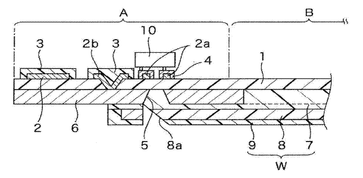
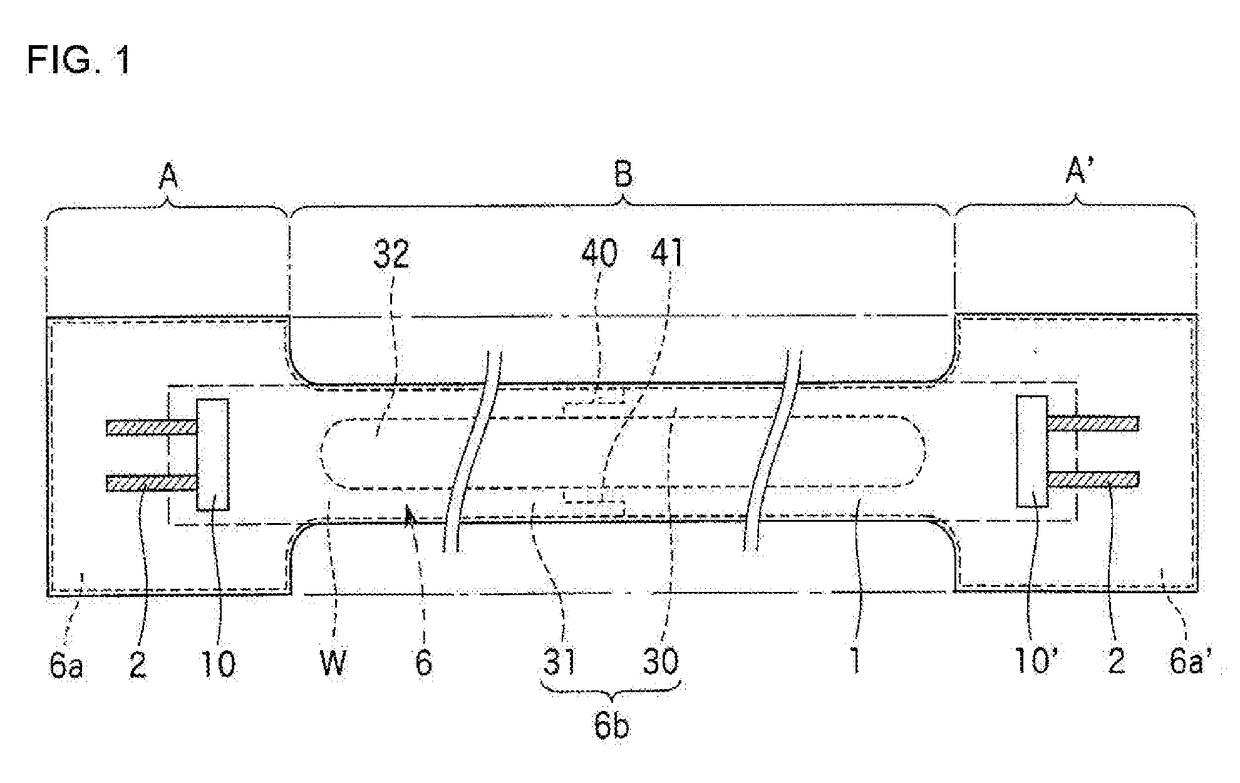
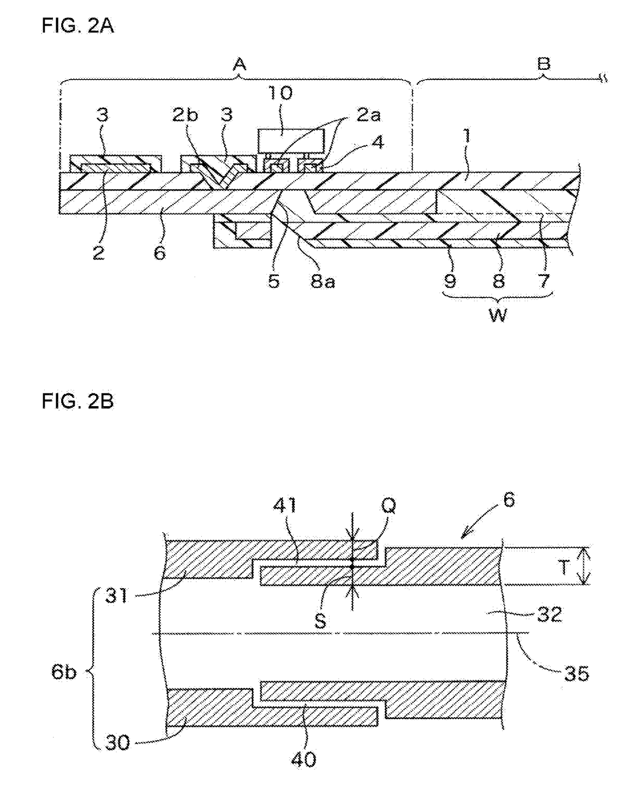
[0067]The opto-electric hybrid board shown in FIGS. 1, 2A and 2B was produced by the aforementioned production method. The interconnection portion B had a length of 20 cm. A 20-μm thick stainless steel layer was provided as the metal reinforcement layer 6. The rounded proximal corner portions of the smaller width portion 6b of the metal reinforcement layer 6 each had a curvature radius of 1.5 mm. The two elongated portions 30, 31 (see FIG. 2B) each had a width T of 400 μm, and the discontinuities 40, 41 each had a width of 100 μm. Since the portions of the elongated portions 30, 31 separated widthwise from each other had a total width (Q+S) of 400 μm, the ratio T:(Q+S)=1:1. The insulation layer 1 had a thickness of 5 μm, and the under-cladding layer 7 had a thickness of 10 μm (as measured from the back surface of the insulation layer 1). The core 8 had a thickness of 50 μm and a width of 50 μm. The over-cladding layer 9 had a thickness of 70 μm (as measured from the surface of the u...


PUM


Abstract

An opto-electric hybrid board includes opto-electric module portions respectively defined on opposite end portions of an elongated insulation layer, and an interconnection portion defined on a portion of the insulation layer between the opto-electric module portions and including an optical waveguide. A metal reinforcement layer extends over the opto-electric module portions into the interconnection portion. A portion of the metal reinforcement layer present in the interconnection portion has a smaller width than portions of the metal reinforcement layer present in the opto-electric module portions, and has a discontinuity extending widthwise across the metal reinforcement layer. This arrangement makes it possible to protect the optical waveguide from the bending and the twisting of the interconnection portion, while ensuring the flexibility of the interconnection portion including the optical waveguide.

Description

TECHNICAL FIELD[0001]The present invention relates to an opto-electric hybrid board including an opto-electric module portion and an interconnection portion.BACKGROUND ART[0002]In recent electronic devices and the like, optical wirings are employed in addition to electric wirings to cope with increase in information transmission amount. With a trend toward size reduction of the electronic devices and the like, there is a demand for a wiring board which has a smaller size and a higher integration density so as to be mounted in a limited space. For example, an opto-electric hybrid board as shown in FIG. 7A is proposed as such a wiring board, in which an opto-electric module portion E including an electric wiring 13 of an electrically conductive pattern and an optical element 10 mounted on pads 13a is provided on each (or one of opposite end portions of a front surface of an insulation layer 12 such as of a polyimide, and an optical waveguide W including an under-cladding layer 20, a c...

Claims


Application Information

Patent Timeline
Patent Type & Authority Applications(United States)
IPC IPC(8): G02B6/12H05K1/02G02B6/42
CPCG02B6/12H05K2201/10121H05K1/0274G02B6/428G02B6/43H01L33/62H01L31/02325G02B6/4214G02B6/4274H01L25/167H01L33/58H05K3/0061H05K2201/2009H01L31/0232H05K1/02
Inventor SHIBATA, NAOKITSUJITA, YUICHI
Owner NITTO DENKO CORP
Why Eureka
Try Eureka