
Electric spraying sterilization and protein peptide bond cleavage device and method

a technology of protein peptide and electric spraying, which is applied in the field of new electric spraying sterilization and protein peptide bond cleavage devices, can solve the problems of high equipment requirements, high energy consumption, risk factors, etc., and achieve the effect of small amount of liquid that can be processed per unit tim

Active Publication Date: 2017-04-27
ZHEJIANG HAOCHUANG BIOTECH
View PDF0 Cites 0 Cited by
  • Summary
  • Abstract
  • Description
  • Claims
  • Application Information

AI Technical Summary

Benefits of technology

This patent gives a new way to use electricity to sterilize liquid food. The invention uses Taylor cone techniques, which are commonly used in electric spray ionization, to create a highly effective sterilization effect. The invention overcomes the limitation of slow flow rate and uses atomization technology to spray a liquid into a large number of droplets. This creates countless Taylor cones, which are small enough to be counted on the sub-micron level so that the surface electric field action on the liquid is strong enough to fully polarize the microbial cells with polarity, thoroughly disrupting them to achieve the effect of sterilizing. The invention also features a hollow cylinder and a water channel, which greatly improve the amount of liquid that can be processed per a unit time. Overall, this invention has a simple structure, easy operation, and better and more thorough sterilization effects, making it suitable for industrial applications.

Problems solved by technology

As PEF technology requires high intensity pulsed electric voltages, it inevitably involves high energy consumption, high technical requirements for equipment, and risk factors associated with high voltage.
More critically, PEF technology fails to ensure uniform electric field intensity for liquids of diverse physical and chemical parameters.
When used to sterilize liquid food products, PEF technology can produce unstable and unreliable sterilizing effects.
Unfortunately, the inner diameter of the outlet end of the hollow capillary emitter is small, such that the amount of liquid that can be processed per unit time is small.
Therefore, the prior electrospraying approach is not suitable for treating large quantities of liquid within reasonable periods of time.

Method used


Image

  • Electric spraying sterilization and protein peptide bond cleavage device and method
  • Electric spraying sterilization and protein peptide bond cleavage device and method
  • Electric spraying sterilization and protein peptide bond cleavage device and method

Examples


example 1

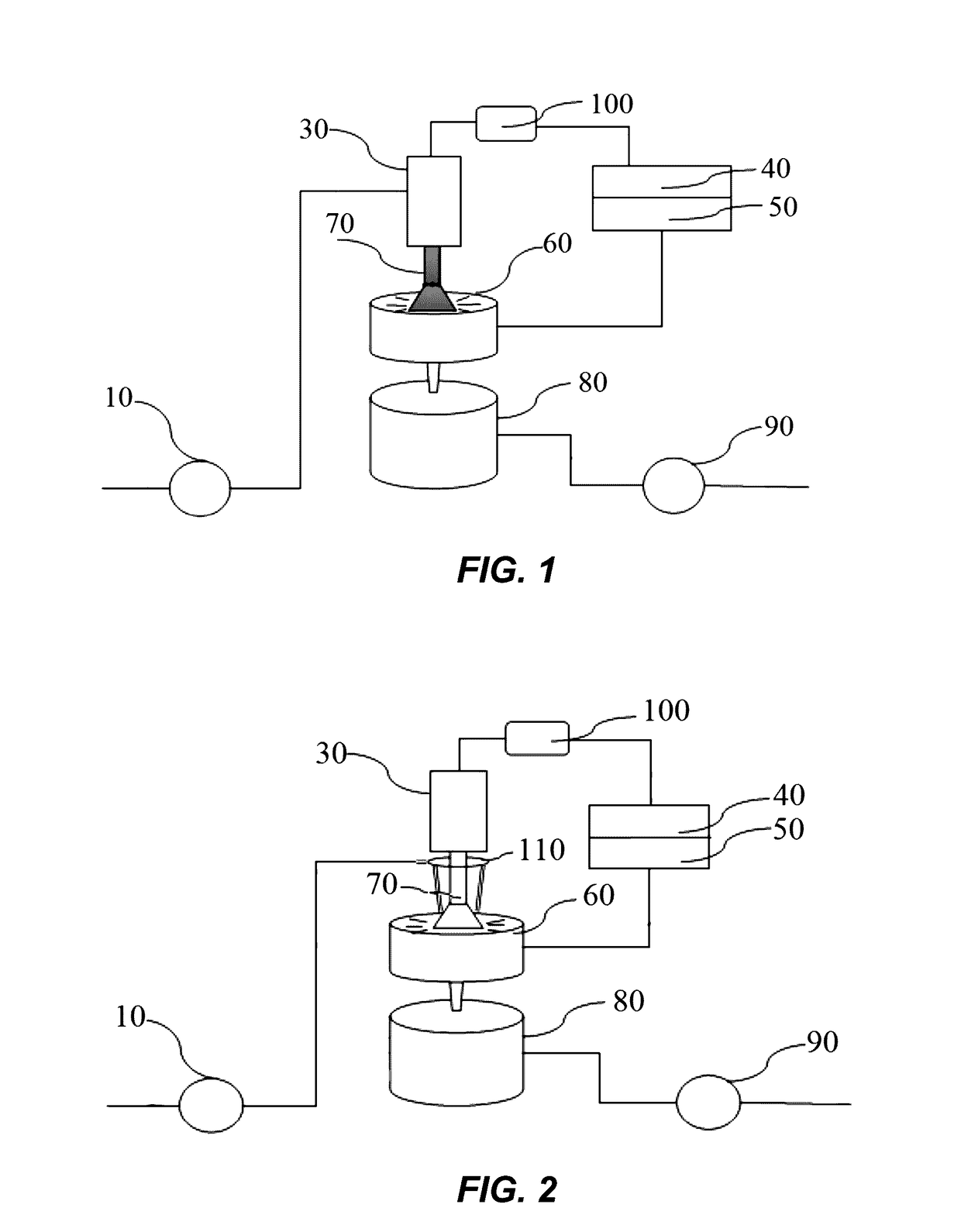
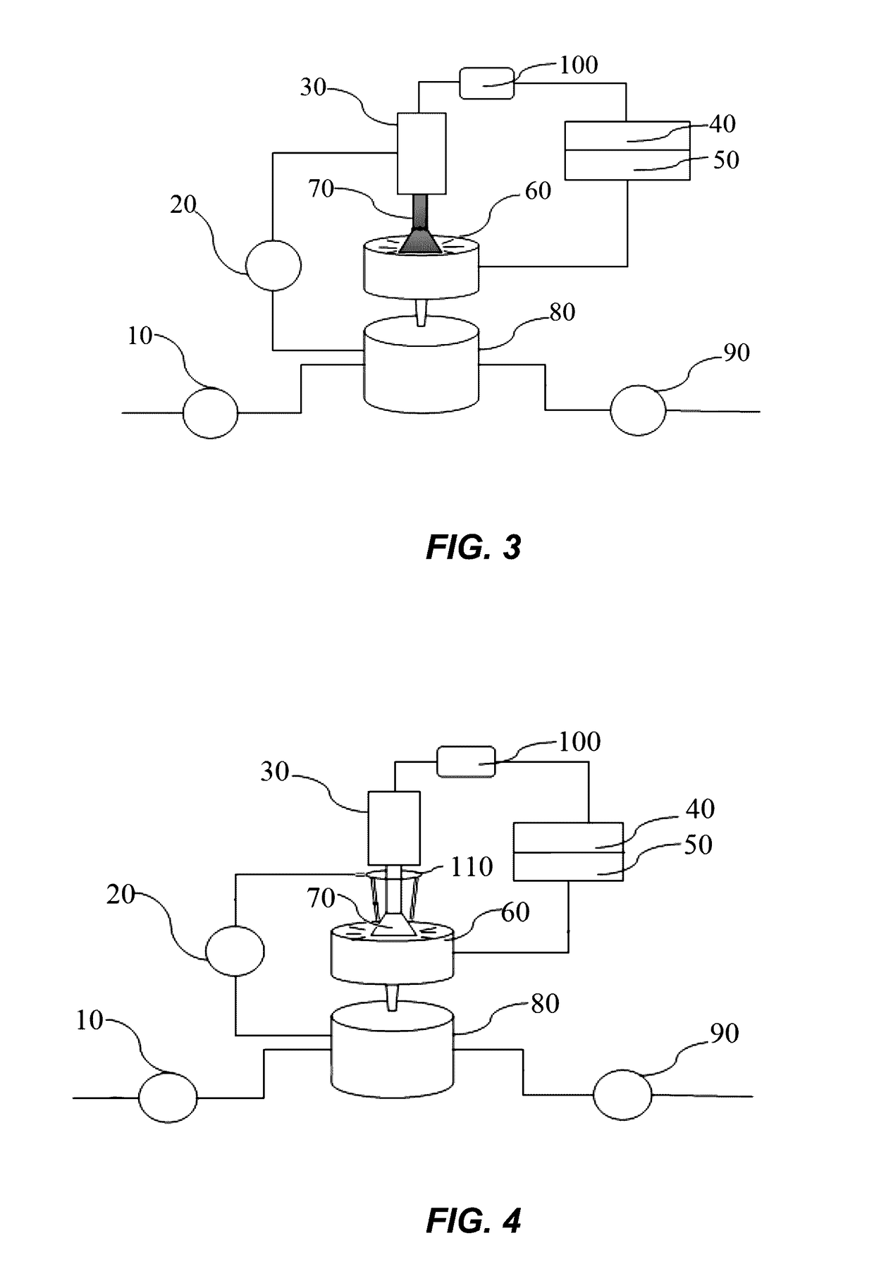
[0044]FIGS. 1, 5, and 8 show an example electric spraying sterilization and protein peptide bond cleavage device, which includes a feed pump 10, an electric voltage device 40, and an atomization device 30. One pole (anode or cathode) of the electric voltage device 40 connects with an electrode container 60 via a cable, while the other pole connects with the atomization device 30 via an isolation transformer 100. The atomization device 30 is provided with a liquid inlet and a liquid outlet. The liquid outlet is connected with a spray emitter, which is made of conductive materials and has an outlet for dispensing liquid into the electrode container 60, which is also made of metal material. The electrode container 60 is connected to a transfer container 80, which further connects with a discharge pump 90 by a pipe. The inside surface of the transfer container 80 is made of metal material, connecting to ground with grounding wire. The atomization device 30 has an inlet / outlet connected ...

example 2

[0045]FIGS. 1, 5, and 8 show an example electric spraying sterilization and protein peptide bond cleavage device, with a difference from Example 1 being that there are multiple parallel annular blade ports 72 arranged at the bottom of the trumpet-shaped portion of the trumpet type spray emitter 70.

[0046]A specific sterilization process for Example 2 and Example 3 (below) is that liquid from the feed pump 10 flows into the atomizer, goes through the liquid outlet to the inside of the hollow cylinder of the spray emitter, and then flows along the horn body of the trumpet type spray emitter while continuously being atomized. At the same time, the liquid forms numerous continuous dynamic Taylor cones at the exit end under the double effect of the electric field force. Thus, high electric field areas are formed on the surface of the Taylor cones. Bacteria passing through the high electric field areas will be fully polarized, becoming thoroughly disrupted or electroporated and ultimately ...

example 3

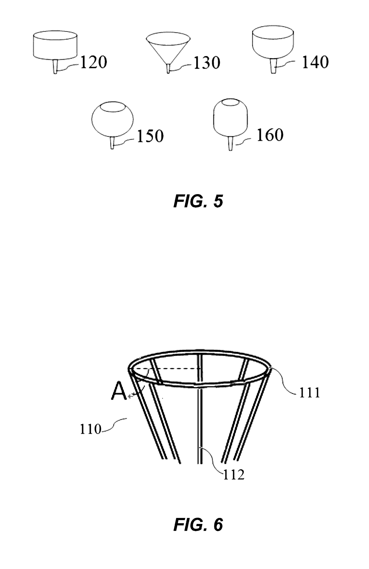
[0047]FIGS. 2, 5, and 8 show an example electric spraying sterilization and protein peptide bond cleavage device, which includes a feed pump 10, an electric voltage device 40, and an atomization device 30. One pole (anode or cathode) of the electric voltage device 40 connects with an electrode container 60 via a cable, while the other pole connects with the atomization device 30 via an isolation transformer 100. The atomization device 30 is connected with the spray emitter, which is made of conductive materials. A multi feeder 110 is disposed outside the spray emitter. The multi feeder 110 is provided with an annular duct 111. The surface of the multi feeder 110 is arranged on water channels 112 (e.g., ten water channels), which are communicated with the annular duct 111. The water channels 112 are uniformly arranged along the circumference of the multi feeder surface, whose included angle A formed with the annular duct is 60 degrees, for example. The spray emitter is configured to ...


PUM


Abstract

An electric spraying device includes a spray emitter made of electrically conductive material, an electrode container made of electrically conductive material, and a voltage source. The electrode container has an opening at an upper end thereof, and the voltage source has a first pole electrically coupled to the spray emitter and a second pole electrically coupled to the electrode container. The spray emitter has an exit end disposed at or within the opening of the electrode container. The exit end of the spray emitter has a surface with a set of projections extending therefrom, and the set of projections are configured to form a concentrated electric field in response to an applied voltage from the voltage source between the first pole and the second pole. The spray emitter is constructed and arranged to conduct liquid along the surface to the set of projections, so as to polarize the liquid under the concentrated electric field and to dispense the liquid into the electrode container.

Description

CROSS-REFERENCES TO RELATED APPLICATIONS[0001]This application claims the benefit of Chinese Patent Application No. 2015 / 208321392, filed Oct. 23, 2015, the contents and teachings of which are incorporate herein by reference in their entirety.BACKGROUND[0002]1. Field of the Invention[0003]The present invention relates generally to liquid food sterilization, and more specifically to a new electric spraying sterilization and protein peptide bond cleavage device.[0004]2. Description of the Related Art[0005]Known approaches for sterilizing materials apply high intensity pulsed electric fields (PEF) to liquids to cause bacteria in the liquids to electroporate and consequently inactivate. As PEF technology requires high intensity pulsed electric voltages, it inevitably involves high energy consumption, high technical requirements for equipment, and risk factors associated with high voltage. More critically, PEF technology fails to ensure uniform electric field intensity for liquids of div...

Claims


Application Information

Patent Timeline
Patent Type & Authority Applications(United States)
IPC IPC(8): A23L3/32
CPCA23V2002/00A23L3/32
Inventor ZHU, YIXINLU, TINGTINGGE, LINZEWANG, SHENGCHUN
Owner ZHEJIANG HAOCHUANG BIOTECH
Learn More