
Rotating, self-excited, asymmetric radio frequency resonant cavity turbine for energy storage and power production

a radio frequency resonant cavity, self-excitation technology, applied in the direction of machines/engines, magnetic bearings, steam turbines, etc., can solve the problems of limited power generation capacity of steam, hydraulic, wind and combustion turbines, and limited energy input into their shaft systems

Active Publication Date: 2017-04-27
CURRIE ANDREW
View PDF0 Cites 3 Cited by
  • Summary
  • Abstract
  • Description
  • Claims
  • Application Information

AI Technical Summary

Benefits of technology

This patent describes a new type of rotor that can store and generate much higher energy levels than current turbines. By using a special type of force called asymmetric radio frequency resonant cavity, the rotor can achieve higher energy storage and power potential. This new turbine can be used in a variety of applications, such as powering machines or generating electric power. It offers the advantage of producing ultra high rotational speed and inertia for consumption by a connected load.

Problems solved by technology

Production of rotating energy via a prime mover to power a shaft system or a rotating generator is typically limited to mass impulse, fluid pressure reaction turbines, or a combination thereof.
Typical modern prime mover turbines employed in the power production industry have limitations of energy input into their shaft systems which are constrained by their turbines fluid properties and or the turbine fluid's enthalpy.
In other words, steam, hydraulic, wind and combustion turbines are limited in their ability to produce power (rotating speed and torque) by way of the limiting properties of their working fluids.
As such, storage of energy generated by a turbine into a rotating mass is then limited by the fluid dynamic and thermodynamic constraints of the working fluids.
The principle limitation is that of the energy input method.
Modern prime movers such as electric motors, fluid turbines, combustion turbines, rotating reciprocating engines, etc. all have the limitations of fluid impulse rate, reactive fluid pressure reduction, gaseous expansion, and or limited rotating electromagnetic field speeds.
This creates maximum rotational speed limitations on the rotating shaft system.
For motors it is the limitation of power available produced from another prime mover or potential energy source that limits rotational speed principally.
A low power exciter input into the shaft system will result in time accumulated energy storage magnitudes beyond the present modern art.
These modern turbines all are limited in terms of shaft power output in terms of the working fluids pressure and velocity.
As such, a force (and thus torque) of a constant nature, which does not separate itself from the imparted rotating mass will permit unceasing energy injection into the rotating elements of the shaft system.
Other classes of conventional thrusters such as ion thrusters and propellant powered thrusters require for their process a finite volumetric fuel or mass supply and are subject to the limitations of its working fluids and exhaust velocities.
As a result of a finite fuel supply other thrusters utilized on a shaft system would have little design benefits in that the impulse imparted to the rotating shaft system would be over a relatively small time period only if independently fueled.
Any permanantly supplied mass fuel would also limit a rotor speed by virtue of it fluid dynamic properties.
These Newtonian turbines all are limited in terms of shaft power output in terms of the working fluids pressure and velocity.
As such, a force (and thus torque) of a constant nature, which does not separate itself from the imparted rotating mass will permit unceasing energy injection into the rotating elements of the turbine shaft system.

Method used


Image

  • Rotating, self-excited, asymmetric radio frequency resonant cavity turbine for energy storage and power production
  • Rotating, self-excited, asymmetric radio frequency resonant cavity turbine for energy storage and power production

Examples


first embodiment

—FIG. 1—First Embodiment

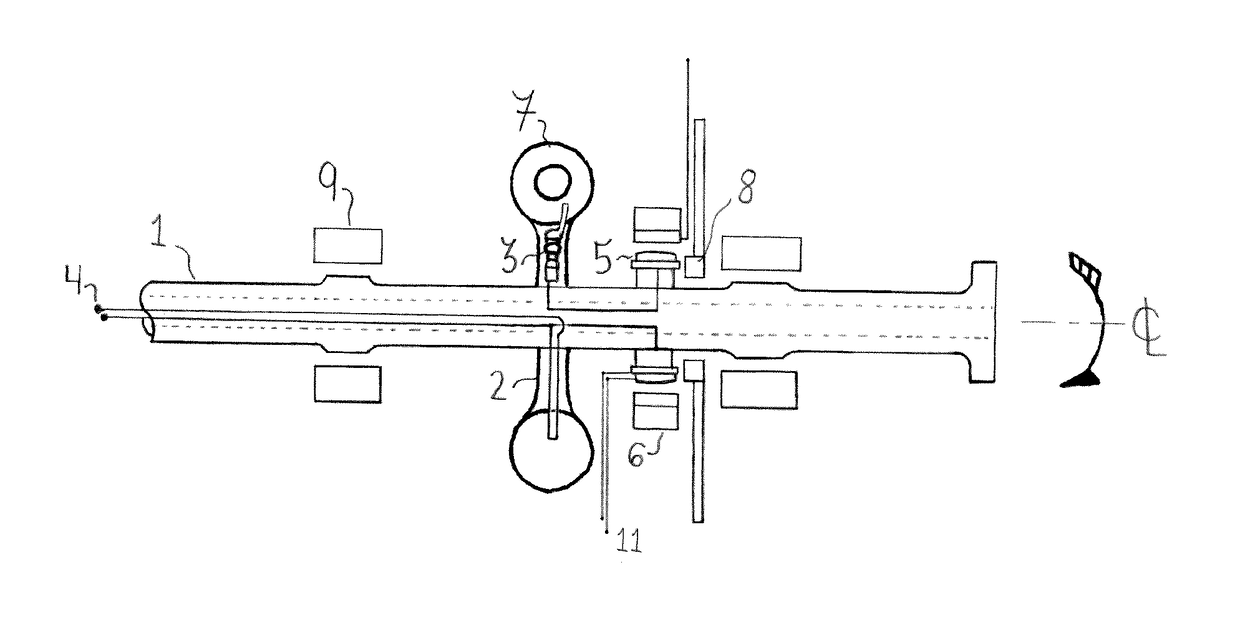
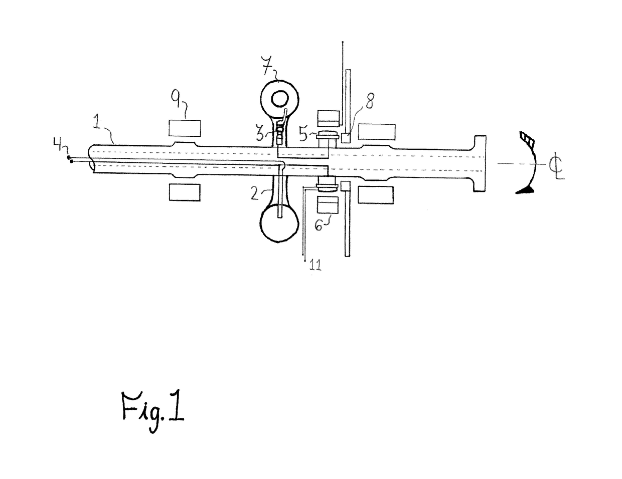
[0046]FIG. 1 shows a cross sectional view of one embodiment of the asymmetric radio frequency resonant cavity turbine for energy storage and power production. Shown in the figure is a main shaft 1. Connected to the main shaft 1 are torque transfer mechanisms (Arms depicted, however can embody any typical arrangement such as a Hub or force coupled rotor body) 2. The arms 2 are linked integrally in terms of mechanical strength to the Asymmetric Radio Frequency Resonant Cavities 7. The cavities 7 are thrusters 7. Adapted microwave generators 3 such as adapted Klystron Tubes 3 are connected to the thrusters 7 and feed the thruster 7 the necessary electromagnetic signal required for thrust production. The Microwave generators 3 are also linked to an excitation system 5 which can receive outside power input or self excite utilizing rotational inertia converted through the generator and an exciter 10. The microwave generators 3, and thrusters 7 are cooled with a flu...


PUM


Abstract

Disclosed is a new classification of Turbine Prime Mover, capable of producing high magnitudes of rotational speed, potential rotating energy and power production. The invention is a rotating machine adapted to be propelled by the net force created by asymmetric radio frequency resonant cavities (7). The turbine employs thrusters (7) electrically driven by microwave signals produced from adapted Klystron Tubes (3). By optimizing microwave production, and thruster pressures via the internal radio frequency cavity resonance, power in the field of the thruster by wave tube amplification, internal reflectivity and cooling, the principles of rotor-dynamics are applied to produce a new class of energy storage machine. Low power inputs yield high energy magnitudes over time accumulated thruster operation in the rotor. The turbine rotor is capable of acting as a prime mover for energy injection into a rotor mass, or can create real work by outputting rotational energy into torque.

Description

CROSS-REFERENCE TO RELATED APPLICATIONS[0001]This application claims the benefit of provisional patent application Ser. No. 62 / 244,526, filed 2015 Oct. 21, by the present inventor.BACKGROUND[0002]Field of Invention[0003]The present invention relates to the technical field of rotating electrical machines, in particular high speed (Greater than 1000 rpm) Rotor Generators and Turbine Shaft Systems utilized in the utility power production field.[0004]Prior Art[0005]The following is a tabulation of some prior art that presently appears relevant:U.S. Patents[0006]Publication Nr.Kind CodePubl. DateApplicantUS20140013724A12014 Jan. 16Guido P. FettaNonpatent Literature Documents[0007]“Anomalous Thrust Production from an RF Test Device Measured on a Low-Thrust Torsion Pendulum”, David Brady, Harold White, Paul March, James Lawrence, Frank Davies, NASA Lyndon B. Johnson Space Center, Houston, Tex. 77058.[0008]“Net thrust measurement of propellantless microwave thrusters”, Yang Juan, Wang Yuqua...

Claims


Application Information

Patent Timeline
IPC IPC(8): F02M27/04H02K7/18
CPCF02M27/04H02K7/1807Y10S74/09H02K53/00F16C32/0406F16C2360/00H02K7/1823H02K99/00H02K99/10H02K99/20F16C32/0489
Inventor CURRIE, ANDREW
Owner CURRIE ANDREW
Learn More