Method for cutting polarizing plate and polarizing plate cut using same

Active Publication Date: 2017-05-04
SHANJIN OPTOELECTRONICS SUZHOU CO LTD
View PDF3 Cites 5 Cited by
  • Summary
  • Abstract
  • Description
  • Claims
  • Application Information

AI Technical Summary

Benefits of technology

The present invention provides a polarizing plate cut which has excellent quality with no deformation on the cut surface and minimal fume generation. When used in a liquid crystal cell, it results in a display device with improved appearance and optical characteristics while reducing bubble generation. The method for cutting the polarizing plate is easy to apply to large plates and improves productivity.

Problems solved by technology

However, the cellulose-based optical film as described above has disadvantages in that the film does not have sufficient wet heat resistance, and thus polarization performances such as a polarization degree and a color easily deteriorate under high temperature and high humidity environments and the interface between an optical film and a polarizer is easily peeled off.
Further, since a phase difference with respect to incident light in an inclination direction is produced, there is a problem in that viewing angle characteristics of a liquid crystal display device, which is gradually enlarged, are affected, and thus, recently, cyclo olefin-based optical films, which are excellent in heat resistance and optical transparency, have been actively used as the optical film.
However, with the recent trend of enlarging a liquid crystal display device, a need for cutting and grinding processes in order to obtain a polarizing plate cut into a large size has increased, but there is a problem in that the production costs are increased because the technology of cutting a polarizing plate with a large size by using a knife has been insufficiently developed and additional process facilities are required.
Further, in the case of the cutting using a knife, in order to secure excellent quality of the cut surface with cracks or wear and tear on the cutting blade of the knife, the cutting blade of the knife needs to be periodically exchanged, thereby leading to a problem in that production costs are increased.
However, a polarizing plate including a cyclo olefin-based optical film has an absorption wavelength of a laser light different from that of a cellulose-based optical film usually used in the related art, and thus there occurs a problem in that excessive heat is applied to the polarizing plate in order to cut the polarizing plate, and accordingly, the cut surface of the polarizing plate is deformed.
If a cut surface is deformed as described above, adhesion deteriorates when the cut surface is laminated with a liquid crystal cell, and thus a large amount of bubbles are generated on the laminated surface close to the cut surface, and foreign substances such as dust produced due to excessive heat cause appearance defects of a liquid crystal display device, thereby leading to a problem in that loss is generated during the production processes to significantly degrade the productivity.

Method used


Image

  • Method for cutting polarizing plate and polarizing plate cut using same
  • Method for cutting polarizing plate and polarizing plate cut using same
  • Method for cutting polarizing plate and polarizing plate cut using same

Examples


example 1

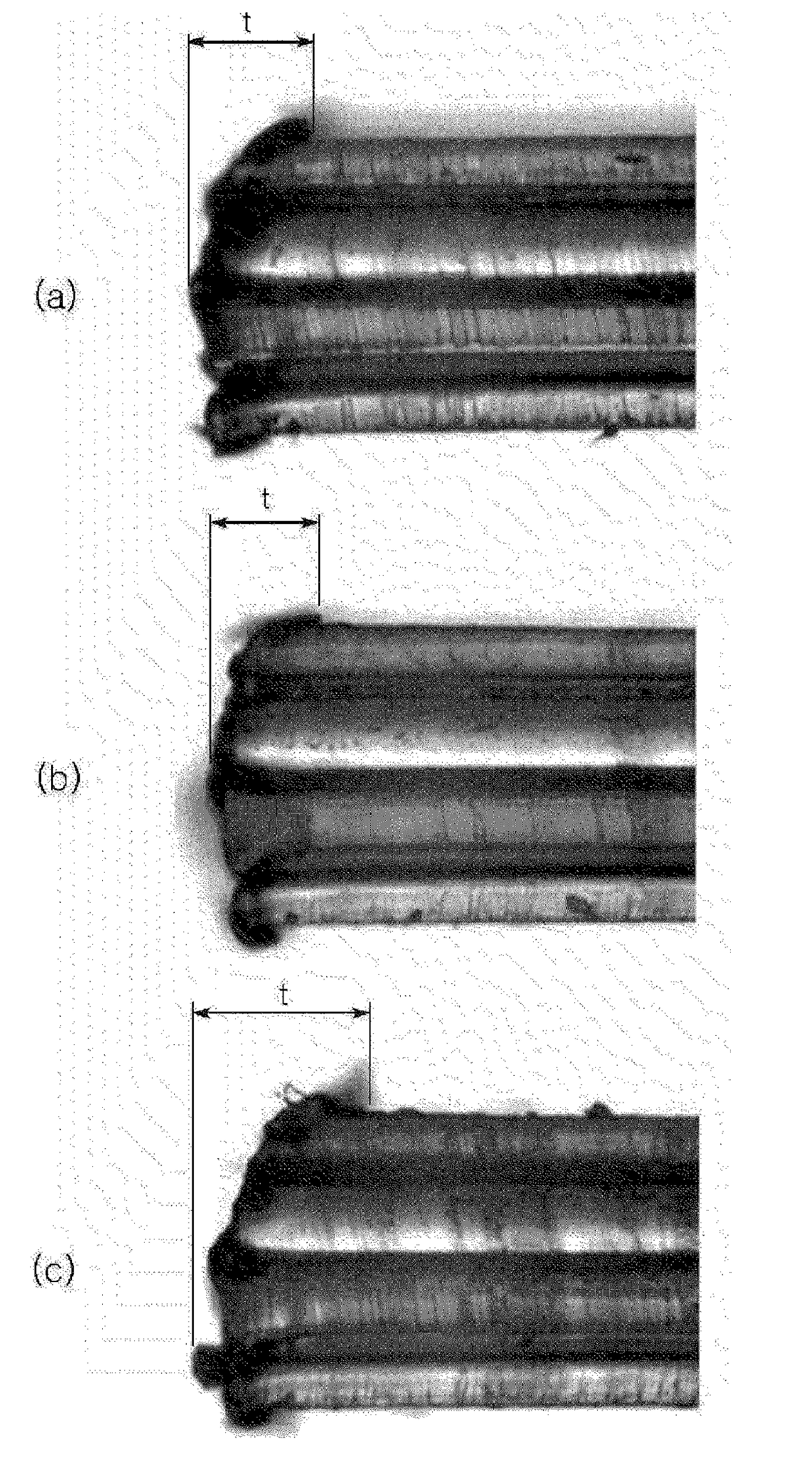
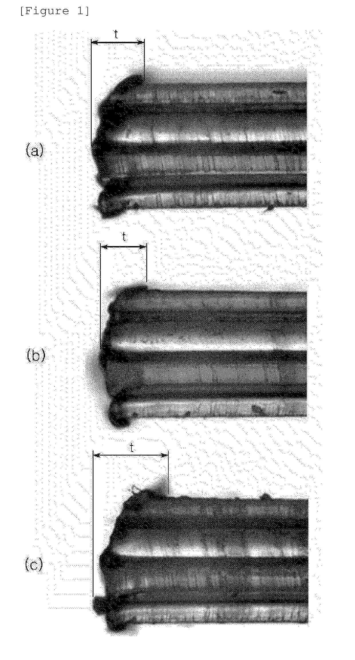
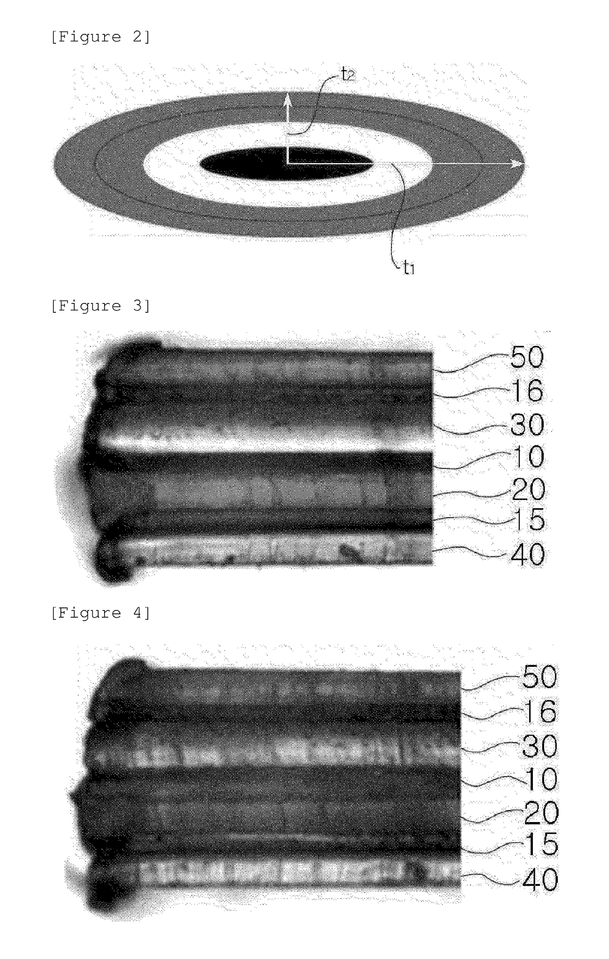
[0052]A polarizing plate in which a PET film / a TAC film / a PVA polarizing element / a COP film / a tackifier layer / a PET film were stacked in this order was cut in a direction that is the same as the stretching direction of the polarizing plate by using a laser having a beam shape of an ellipse with a ratio of major axis to minor axis of 1:0.5. In this case, the COP film used had a thickness of 60 μm, and the polarizing plate had a thickness of 250 μm. Furthermore, the laser light required to cut the polarizing plate had a minimum pulse energy of 5.4 mJ, and the cutting speed of 333 mm / s.

example 2

[0053]A polarizing plate was cut in the same manner as in Example 1, except that the polarizing plate was cut in a direction vertical to the stretching direction of the polarizing plate. In this case, the laser light required to cut the polarizing plate had a minimum pulse energy of 6.4 mJ, and the cutting speed of 700 mm / s.

example 3

[0054]A polarizing plate was cut in the same manner as in Example 1, except that a COP film having a thickness of 40 μm was used and the polarizing plate had a thickness of 230 μm. In this case, the laser light required to cut the polarizing plate had a minimum pulse energy of 5 mJ, and the cutting speed of 333 mm / s.


PUM

PropertyMeasurementUnit
Thicknessaaaaaaaaaa
Thicknessaaaaaaaaaa
Thicknessaaaaaaaaaa

Abstract

The present invention relates to a method for cutting a polarizing plate using a laser, in which a beam shape of the laser is an elliptical shape and a major axis of the elliptical shape is parallel to a cutting direction, and a polarizing plate cut using the same.

Description

TECHNICAL FIELD[0001]This application claims priority to and the benefit of Korean Patent Application No. 10-2014-0130819 filed in the Korean Intellectual Property Office on Sep. 30, 2014, the entire contents of which are incorporated herein by reference.[0002]The present invention relates to a method for cutting a polarizing plate using a laser.BACKGROUND ART[0003]Since a liquid crystal display device has low power consumption and a small volume and is light and thus easy to carry, compared to a cathode ray display, the liquid crystal display has been rapidly distributed as an optical display element. In general, the liquid crystal display (LCD) device includes a liquid crystal layer and a polarizing plate stacked on both surfaces of a liquid crystal cell composed of a transparent glass substrate or a plastic-based sheet material as a base configuration.[0004]Meanwhile, the polarizing plate usually includes a polarizing element composed of a polyvinyl alcohol (hereinafter, referred...

Claims


Application Information

Patent Timeline
IPC IPC(8): B23K26/38B23K26/06
CPCB23K26/38B23K2203/42B23K26/0626B23K26/0736B23K26/402G02B5/3033B23K26/0622B23K2103/54B23K2101/00B23K2101/34B23K2103/172B23K2103/42B23K26/067
Inventor LEE, BEOM SEOKJANG, EUNG JINLEE, SUKJAE
Owner SHANJIN OPTOELECTRONICS SUZHOU CO LTD
Why Eureka
Try Eureka