Method for Generating Electrical Energy by Laser-Based Nuclear Fusion and Laser Reactor

a laser reactor and nuclear fusion technology, applied in nuclear reactors, nuclear energy generation, reaction to electrical energy, etc., can solve the problems of extreme, catastrophic damage, cost and risk of radioactive waste disposal, etc., and achieve the effect of optimal adaptation

Active Publication Date: 2017-05-04
UJK MANAGEMENT +1
View PDF1 Cites 11 Cited by
  • Summary
  • Abstract
  • Description
  • Claims
  • Application Information

AI Technical Summary

Benefits of technology

[0037]If, according to a further variant of the invention, the energy conversion device is at ground potential, advantages with respect to the configuration of the nuclear fusion reactor and the feeding thereof with fusion fuel are achieved. The energy conversion device is preferably in the form of a spherical, electrically conductive enclosure (housing) around the reaction chamber, in particul

Problems solved by technology

As a disadvantage, however,this process releases the combustion product carbon dioxide into the atmosphere, which can lead to undesirable changes in global climate.
Although the operation of nuclear power plants is economical, it has the disadvantage that the disposal of radioactive waste is costly and risky.
Furthermore, it involves the operational risk that a power plant accident can result in extreme, catastrophic damage.
However, with the exception of natural processes occurring in stars, nuclear fusion has heretofore been realized only in an uncontrolled manner in the form of exploding a fusion bomb.
Controllable fusion power plants have been in development for decades, however despite major research efforts, they have not yet been successfully implemented in practice.
H

Method used


Image

  • Method for Generating Electrical Energy by Laser-Based Nuclear Fusion and Laser Reactor
  • Method for Generating Electrical Energy by Laser-Based Nuclear Fusion and Laser Reactor
  • Method for Generating Electrical Energy by Laser-Based Nuclear Fusion and Laser Reactor

Examples


Embodiment Construction

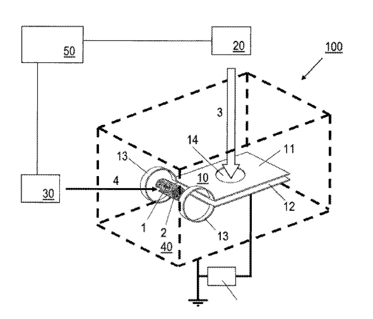
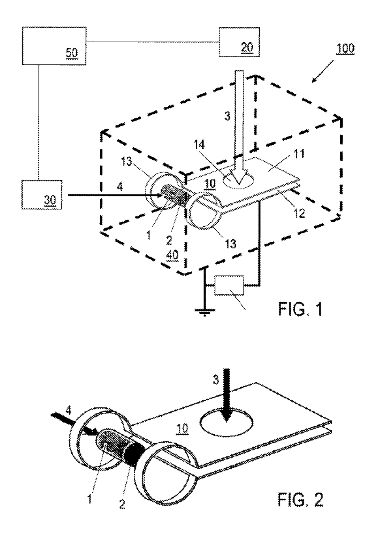
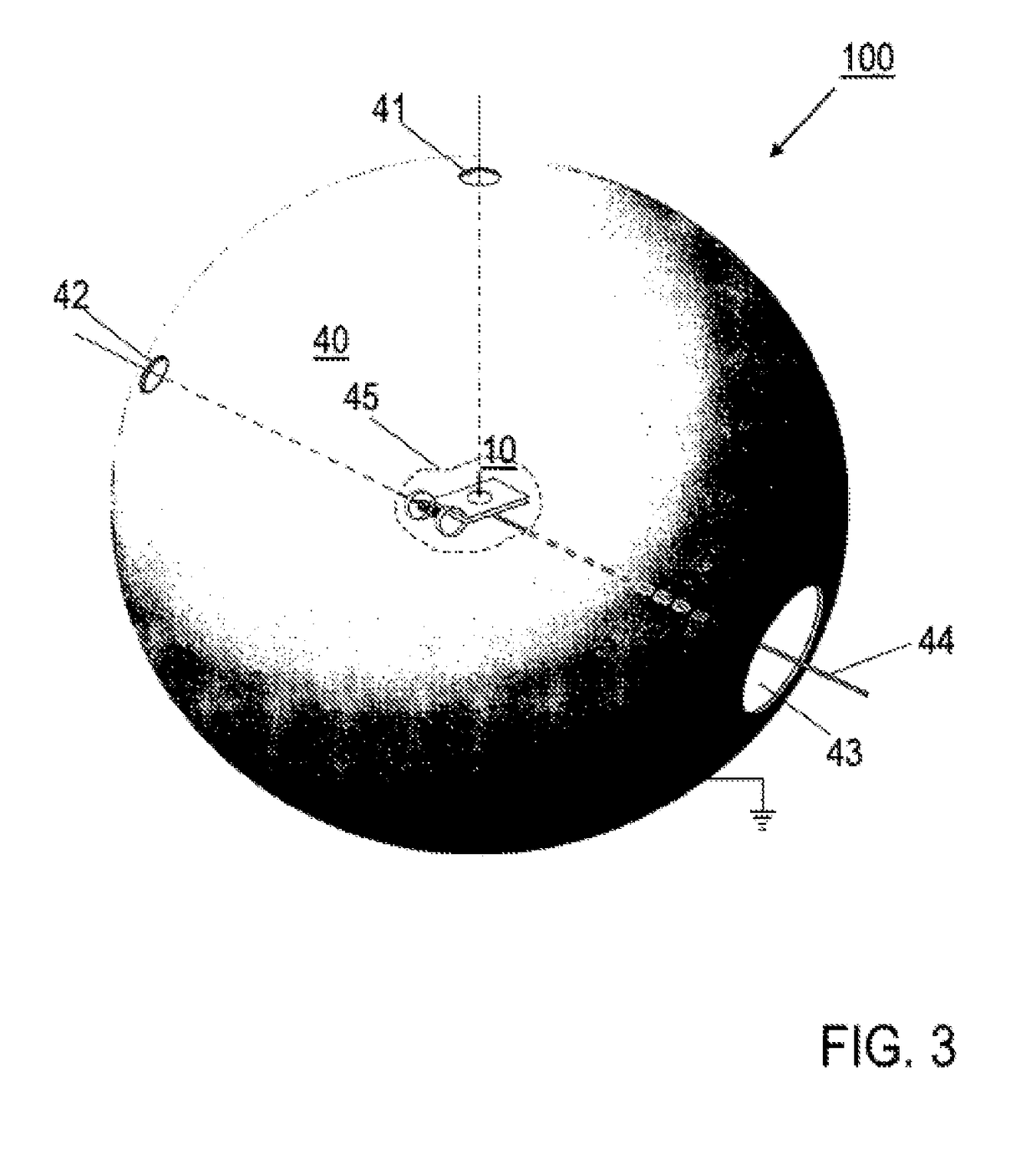
[0048]Features of preferred embodiments of the invention are described below primarily with reference to the generation of the magnetic field for holding the fusion fuel and the design of the energy conversion device. Details the invention,such as the details of laser pulse sources, the physical principles of the HB11 reaction, the connection of the fusion reactor to other components of a power plant, in particular for preparing and delivering the fusion fuel, for controlling the fusion reactor, for protecting; the environment against thermal effects and / or electric fields, are not described, as these can be realized by a person skilled in the art based on his / her knowledge of known fusion and plasma physics and conventional power plant engineering, depending on the specific conditions of use of the invention. Reference is made by way of example to a fusion reactor having a single reaction chamber. However, the invention is not limited to this design. Rather, a fusion reactor be equ...


PUM


Abstract

A method for generating electrical energy, comprising the steps of providing a fusion fuel (1), the fusion fuel (1) being held in a magnetic field within a cylindrical reaction chamber (2), initiating nuclear fusion in the fusion fuel (1), in which a fusion flame is produced by fusion laser pulses (4) having a pulse duration of less than 10 ps and a power of more than 1 petawatt, and converting the energy that is released during the nuclear fusion from the nuclei that are produced into power plant power, wherein the magnetic field has a field strength which is greater than or equal to 1 kilotesla and the nuclear fusion has an energy yield of more than 500 per laser energy of the fusion laser pulses (4) that produce the fusion flame. Also described is a nuclear fusion reactor which is configured for generating electrical energy.

Description

[0001]The invention relates to a method for generating electrical energy, which is based on the fusion of protons with the boron isotope 11 using laser radiation and magnetic fields and converting the energy that is released during the fusion into electrical energy. The invention also relates to a laser fusion reactor, which is configured for generating electrical energy by means of the laser-based fusion of protons with the boron isotope 11. Uses for the invention are provided in the field of electric power generation.PRIOR ART[0002]In the e description of the prior art, reference is made to the following publications:[0003][1] J. Nuckolls and L. Wood, Citation 25 on p. 13 of H. Hora and G. H. Miley Edward Teller Lectures Laser and Inertial Fusion Energy. Imperial College Press, London 2005;[0004][2] H. Hora, Physics of Laser Driven Plasma Wiley, N.Y. 1981, FIGS. 10.18 a & b;[0005][3] R. Sauerbrey, Physics of Plasmas 3, 4712 (1996);[0006][4] H. Hora, J. Badziak et al. Physics of Pl...

Claims


Application Information

Patent Timeline
IPC IPC(8): G21B1/23G21B1/19G21D7/00G21B1/05
CPCG21B1/23G21D7/00G21B1/19G21B1/05G21B1/03G21B3/006Y02E30/00Y02E30/10
Inventor HORA, HEINRICH
Owner UJK MANAGEMENT
Why Eureka
Try Eureka