Power storage device packaging material and power storage device using the same

a technology for power storage devices and packaging materials, which is applied in the direction of cell components, cell component details, other domestic articles, etc., can solve the problems of double-sided batteries that have difficulty in aligning, polyamide films that have poor resistance to electrolyte solutions, and polyamide films that have poor formability, etc., to improve the intimate contact of a base material layer and improve the forming depth

Active Publication Date: 2017-05-18
TOPPAN PRINTING CO LTD
View PDF11 Cites 8 Cited by
  • Summary
  • Abstract
  • Description
  • Claims
  • Application Information

AI Technical Summary

Benefits of technology

[0023]The present invention provides a power storage device packaging material and a power storage device using the same that can improve intimate contact of a base material layer with an adhesive layer and can improve the forming depth so as to enable deep drawing without breaking the adhesive layer or the metal foil.

Problems solved by technology

Metal cans that have been used for packaging materials for lithium ion batteries are being replaced by multilayer films due to their light weight, high heat dissipation, and low manufacturing cost.
The double-sided batteries have a problem of difficulty in aligning when bonding the surfaces of the packaging material to each other.
However, when a deeper recess is formed, pinholes or breakage are more easily caused in forming the packaging material, and thus formability is deteriorated.
A polyamide film has poor resistance to an electrolyte solution that is a content of the lithium ion battery.
When an electrolyte solution unavoidably adheres to the polyamide film in injecting the electrolyte solution during production of the lithium ion battery, the polyamide film will melt and poor appearance may be created.

Method used


Image

  • Power storage device packaging material and power storage device using the same
  • Power storage device packaging material and power storage device using the same
  • Power storage device packaging material and power storage device using the same

Examples


example 1

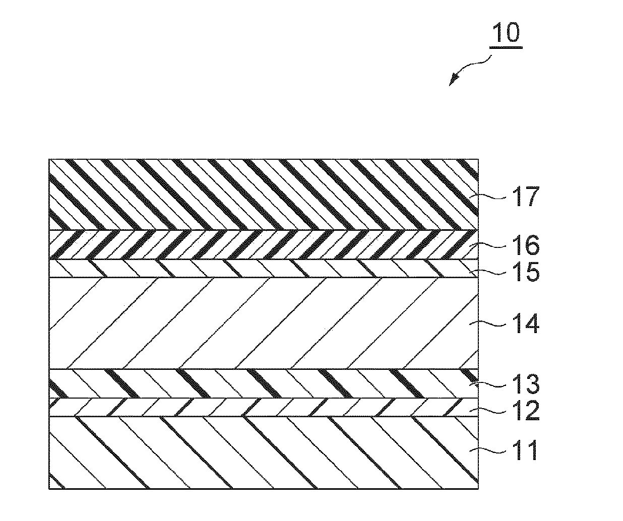
[0215]In Example 1, a power storage device packaging material 10 was prepared by the following method. First, a soft aluminum foil material 8079 (manufactured by TOYO ALUMINIUM K.K.) with a thickness of 40 μm was prepared as a metal foil layer 14. Subsequently, sodium polyphosphate-stabilized cerium oxide sol (anticorrosion agent), in which distilled water was used as a solvent and the solid content concentration was adjusted to 10 mass %, was coated onto a surface of the metal foil layer 14 by gravure coating. In this case, phosphoric acid was 10 parts by mass relative to 100 parts by mass of ceric oxide.

[0216]Subsequently, the coated sodium polyphosphate-stabilized cerium oxide sol was dried, followed by baking, thereby forming an anticorrosion treatment layer 15. In this case, for the baking conditions, the temperature was 150° C., and processing time was 30 seconds.

[0217]Subsequently, a laminate (hereinafter referred to as “laminate P1”) was prepared, in which an adhesion-enhanc...

example 2

[0220]In Example 2, except that the materials for forming the adhesion-enhancing treatment layer 12 were changed to materials below, a power storage device packaging material 10 was prepared similarly to Example 1. An adhesion-enhancing treatment layer 12 of Example 2 was formed by inline coating, in which the coating agent B to serve as the base material of an adhesion-enhancing treatment layer 12 was coated onto a surface of a base material layer 11 (nylon 6 film with a thickness of 25 μm fabricated by sequential biaxial stretching) so as to have a solid content of 0.1 g / m2, followed by drying, thereby forming the adhesion-enhancing treatment layer 12 with a thickness of about 0.1 μm.

example 3

[0221]In Example 3, except that the materials for forming the adhesion-enhancing treatment layer 12 were changed to materials below, a power storage device packaging material 10 was prepared similarly to Example 1. An adhesion-enhancing treatment layer 12 of Example 3 was formed by inline coating, in which the coating agent C to serve as the base material of the adhesion-enhancing treatment layer 12 was coated onto a surface of a base material layer 11 (nylon 6 film with a thickness of 25 μm fabricated by sequential biaxial stretching) so as to have a solid content of 0.1 g / m2, followed by drying, thereby forming the adhesion-enhancing treatment layer 12 with a thickness of about 0.1 μm.


PUM

PropertyMeasurementUnit
tensile speedaaaaaaaaaa
elongationaaaaaaaaaa
breaking strengthaaaaaaaaaa

Abstract

A power storage device packaging material including a base material layer; an adhesion-enhancing treatment layer on a surface of the base material layer; an adhesive layer on a surface of the adhesion-enhancing treatment layer opposite the base material layer; a metal foil layer formed on one side of the adhesive layer opposite the adhesion-enhancing treatment layer; and a sealant layer disposed on a surface of the metal foil layer opposite the adhesive layer. The base material layer is formed of a biaxially oriented film to have a breaking strength of 240 MPa or more in at least one of four directions (0° (MD), 45°, 90° (TD), 135°) and an elongation of 80% or more in at least one direction in a tensile test (test specimen shape: test specimen type 5 stipulated in JIS K7127; inter-chuck distance: 60 mm; tensile speed: 50 mm/min).

Description

CROSS-REFERENCE TO RELATED PATENT APPLICATIONS[0001]This application is a continuation application filed under 35 U.S.C. §111(a) claiming the benefit under 35 U.S.C. §§120 and 365(c) of International Application No. PCT / JP2015 / 070178 filed on Jul. 14, 2015, which is based upon and claims the benefit of priority of Japanese Patent Application No. 2014-145789, filed on Jul. 16, 2014, the entireties of which are hereby incorporated by reference.TECHNICAL FIELD[0002]The present invention relates to a power storage device packaging material and a power storage device using the same.BACKGROUND[0003]Known power storage devices include, for example, secondary batteries, such as lithium ion batteries, nickel hydrogen batteries, and lead batteries, and electrochemical capacitors, such as electric double layer capacitors. Due to downsizing of cellular phones or restriction in installation spaces, and the like, power storage devices are further sought to be downsized, and thus attention is bein...

Claims


Application Information

Patent Timeline
Patent Type & Authority Applications(United States)
IPC IPC(8): H01M2/02H01M2/08H01M50/105H01M50/176H01M50/186H01M50/193H01M50/198H01M50/55H01M50/553
CPCH01M2/08H01M2/0287H01G11/78H01G9/08H01G11/06H01G11/82Y02E60/10H01M50/105H01M50/186H01M50/193H01M50/198H01M50/55H01M50/553H01M50/176B32B7/12B32B15/08B32B27/08B32B2307/518B32B2457/10Y02E60/13H01M50/124H01M50/121H01M50/119H01M50/133
Inventor IJUIN, WATARU
Owner TOPPAN PRINTING CO LTD
Why Eureka
Try Eureka