Fuel injection control apparatus for internal combustion engine

a technology of fuel injection control and internal combustion engine, which is applied in the direction of electric control, combustion engines, pistons, etc., can solve the problems of unstabilized stratified charge combustion, fuel spray may not be able to enter the piston cavity, etc., and achieve the reduction of the chance of generating smoke, pm, and the like, for example, and further reliably suppressed from increasing

Inactive Publication Date: 2017-05-25
TOYOTA JIDOSHA KK
View PDF2 Cites 3 Cited by
  • Summary
  • Abstract
  • Description
  • Claims
  • Application Information

AI Technical Summary

Benefits of technology

[0010]In view of the above, the inventor has reached an idea as a result of earnest researches that the stable stratified charge combustion can be secured by adjusting the momentum (the penetration force) of the fuel spray, which is injected from the fuel injection valve, in accordance with the distance between the fuel injection valve and the piston. More specifically, the inventor has found that the stable stratified charge combustion can be secured by performing so-called “partial lift injection” at an early stage of injection in the compression stroke, at which the distance between the fuel injection valve and the piston is long. The partial lift injection means that the fuel is injected by reducing a maximum value of displacement (that is, an arrival lift amount) of a valve body at a time when the fuel injection valve injects the fuel to be smaller than usual. In the partial lift amount, the momentum (the penetration force) of the fuel spray that is injected from the fuel injection valve can be reduced.
[0012]As described above, in the fuel injection control apparatus according to the one aspect of the invention, the fuel is injected by the split injection at least in the first period of the compression stroke of the internal combustion engine, and the arrival lift amount of the valve body of the fuel injection valve is set as a smaller value as time is closer to an early stage of the first period. In other words, at least the injection at the early stage of the first period is performed in a form of the partial lift injection. In this way, in the case where a distance between the fuel injection valve and the piston is relatively long, momentum (a penetration force) of fuel spray that is injected from the fuel injection valve is small (see FIG. 8B). As a result, a fuel spray amount that cannot enter a piston cavity is reduced as described above, and a fuel spray amount for producing combustible air-fuel mixture with favorable combustibility in the vicinity of an ignition plug is increased. In this way, stable stratified charge combustion can be secured.
[0013]Furthermore, in another aspect of the invention, the electronic control unit may be configured to i) cause the fuel injection valve to inject the fuel at least once in a second period prior to the first period; and ii) set the arrival lift amount such that the arrival lift amount for each injection in the second period is smaller than the arrival lift amount for an initial injection in the first period. According to this, the fuel that is injected in the second period prior to the first period has the extremely small momentum. Such fuel spray does not travel throughout a “combustion chamber that has a large volume due to the long distance between the piston and the fuel injection valve”. Rather, at least some (desirably more) of the fuel spray is likely to remain in the vicinity of the fuel injection valve (an upper section of the combustion chamber). For this reason, the fuel injected in the second period is likely to be caught in the piston cavity when the piston is elevated later, and thus can contribute to production of the combustible air-fuel mixture with the favorable combustibility. As a result, a larger fuel amount can be used to produce the combustible air-fuel mixture.
[0015]In view of the above, in yet another aspect of the invention, the electronic control unit may be configured to i) cause the fuel injection valve to inject the fuel at least once in a third period after the first period; and ii) maintain the arrival lift amount for each injection in the third period at a prescribed value. According to this, it is possible to avoid the arrival lift amount from being set as a larger value at the final stage of the injection in the compression stroke, at which the distance between the fuel injection valve and the piston is short. As a result, as described above, a fuel amount that wets the crown surface of the piston and / or the inner wall of the piston cavity (hereinafter may be referred to as a “wet amount”) is suppressed from increasing. Thus, a chance of generation of the smoke, the PM, and the like, for example, is reduced.
[0016]Alternatively, in further another aspect of the invention, the electronic control unit may be configured to i) cause the fuel injection valve to inject the fuel at least once in the third period after the first period; and ii) set the arrival lift amount such that the arrival lift amount for the each injection in the third period reduces as the crank angle of the internal combustion engine approaches compression top dead center. According to this, the arrival lift amount is set as a smaller value as the time is closer to the final stage of the injection in the compression stroke, at which the distance between the fuel injection valve and the piston is short. As a result, the wet amount is further reliably suppressed from increasing, and the chance of generation of the smoke, the PM, and the like, for example, is further reliably reduced.

Problems solved by technology

However, as indicated by an arrow in FIG. 18A, in the case where the fuel spray with large momentum (a penetration force) (that is, at a high speed) is injected when a distance between the fuel injection valve and the piston is long, the fuel spray may not be able to enter the piston cavity.
As a result, the stratified charge combustion may be unstabilized.

Method used


Image

  • Fuel injection control apparatus for internal combustion engine
  • Fuel injection control apparatus for internal combustion engine
  • Fuel injection control apparatus for internal combustion engine

Examples


first embodiment

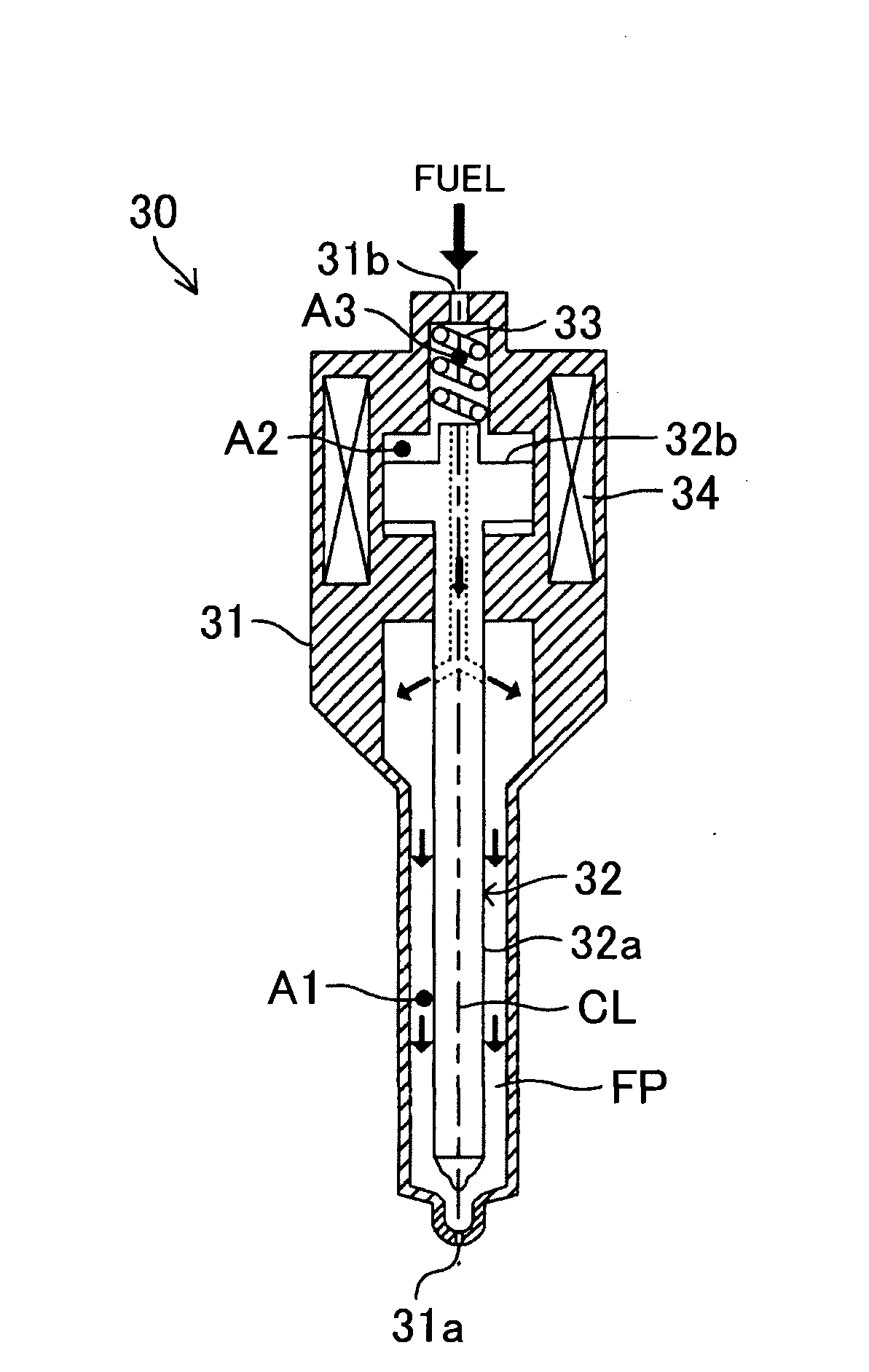
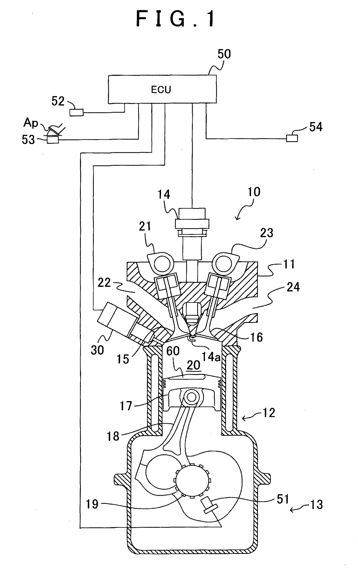
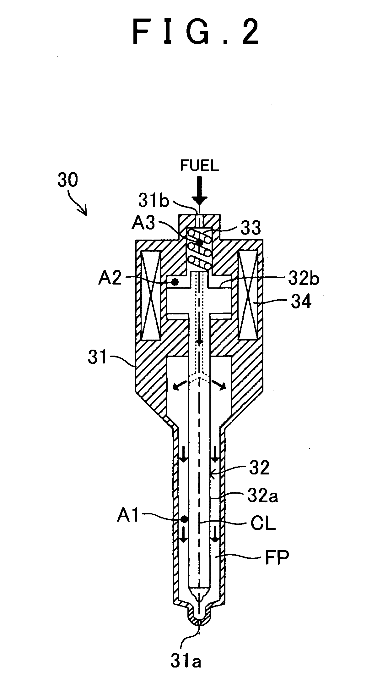
[0037]First, a first embodiment (hereinafter may be referred to as a “first mode”) of the invention is a fuel injection control apparatus for an in-cylinder injection spark-ignition internal combustion engine. The fuel injection control apparatus is applied to an internal combustion engine that includes a piston. The piston is formed with a cavity in a crown surface. The fuel injection control apparatus includes: a fuel injection valve that injects fuel from an injection hole toward the cavity in conjunction with movement of a valve body from a valve seat; and a control section that moves the valve body to inject the fuel from the fuel injection valve and can increase / reduce an arrival lift amount that is a maximum value of displacement of said valve body. In the fuel injection control apparatus, the control section instructs the fuel injection valve to perform split injection, in which the fuel is divided and injected for plural times at least in a first period of compression strok...

second embodiment

[0077]By the way, as described above, for example, in the case where it is difficult to inject the fuel injection amount Q, which is requested per cycle, only by the split injection performed in the first period, the fuel may be injected prior to the above first period. The arrival lift amount in this injection can be set as a larger value or a smaller value than the arrival lift amount for performing the initial injection in the first period. Alternatively, the arrival lift amount in this injection can be set as the same value as the arrival lift amount for performing the initial injection in the first period.

[0078]Here, in a period prior to the first period of the compression stroke of the engine, the distance between the fuel injection valve and the piston is longer than that when the initial injection is performed in the first period. Thus, in order to avoid such a situation that the fuel spray does not enter the piston cavity as described above, the arrival lift amount in the i...

third embodiment

[0082]By the way, as described above, for example, when it is difficult to inject the fuel injection amount Q, which is requested per cycle, only by the split injection performed in the first period, the fuel may be injected after the above first period. The arrival lift amount in this injection can be set as a larger value or a smaller value than the arrival lift amount for performing the final injection in the first period. Alternatively, the arrival lift amount in this injection can be set as the same value as the arrival lift amount for performing the final injection in the first period.

[0083]Here, the piston approaches the fuel injection valve as the crank angle approaches the compression top dead center in the compression stroke of the engine. Accordingly, the distance between the piston and the fuel injection valve is reduced as time is closer to a final stage of the compression stroke. Regardless of this fact, if the momentum (the penetration force) of the fuel spray that is...


PUM


Abstract

In an in-cylinder injection spark-ignition internal combustion engine, in which fuel is injected toward a cavity formed in a crown surface of a piston, when split injection for dividing and injecting the fuel for plural times is performed during a compression stroke, an arrival lift amount that is a maximum value of displacement of a valve body of a fuel injection valve during fuel injection is set as a larger value at least in a first period as a crank angle of the internal combustion engine approaches compression top dead center.

Description

BACKGROUND OF THE INVENTION[0001]1. Field of the Invention[0002]The invention relates to a fuel injection control apparatus for an in-cylinder injection spark-ignition internal combustion engine in which fuel is injected toward a cavity formed in a crown surface of a piston.[0003]2. Description of Related Art[0004]It has been known to directly inject fuel into a cylinder and produce air-fuel mixture with favorable ignitability at a time point of ignition in the vicinity of an ignition plug, so as to perform stratified charge combustion. In the stratified charge combustion, lean air-fuel mixture can be combusted in the entire cylinder. This is effective in improvement of a fuel consumption rate. In the general stratified charge combustion, a fuel injection valve is opened for a period that is required to inject a necessary fuel amount from time at which fuel injection is initiated and which is set in a latter half of a compression stroke. The fuel that is injected just as described e...

Claims


Application Information

Patent Timeline
Patent Type & Authority Applications(United States)
IPC IPC(8): F02D41/30F02F3/28F02D41/40
CPCF02D41/3023F02D2041/389F02F3/28F02D41/402F02D2200/063Y02T10/40
Inventor MITANI, SHINICHIUCHIDA, DAISUKEKANEKO, NAOYAHOSHI, KENJIADACHI, HIROAKIHASHIMOTO, SUSUMU
Owner TOYOTA JIDOSHA KK
Why Eureka
Try Eureka